
Answering Machine User Manual

~
.;;,.~,
'i I:"
;;:.::"0;;.. .
.~;t.~.:.:;
,::~~;~;;
~"
";""N"',;;;; WAbtir:'M O U N](N G t ,,;:ii,~;"'".
.;;:,...,
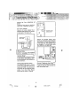
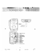
located on the back of the Base
Unit. (Figure 2)
Choose a spot near an electrical
outlet and a telephone jack.
Your phone requires a modular
telephone jack and a standard
electrical outlet (120v AC). The
power cord is six feet long; make
sure there is an electrical outlet
within reach of the base. The outlet
should not be controlled by a wall
switch. If the switch is ever turned
off, the phone ~ill not operate.
9
-<.
Figure 1
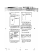
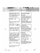
2. Position the wall mounting
bracket on the base.
Line up the tabs on the wall
mounting bracket with the holes
on the bottom of the base {Figure
1 ). Snap the wall mounting bracket
firmly in place.
-
-
-
-
a
~
-@-
+
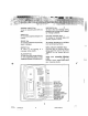
Mount the bas~ on the wall.
Position the base so the mounting
studs will fit into the holes on the
bottom of the base. Position the
power cord to extend down the
wall the phone is to be mounted
on. Slide the base down on the
mounting studs until it locks into
place.
J.-
:0
$
~
Figure 2
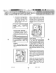
4. Connect the telephone line cord.
The telephone line cord has a
snap-in plug at each end. Insert
one of the plugs into the jack on
the back of the base. Insert the
other end of the plug into the wall
jack.
5. Plug the AC adapter into an
electrical outlet and the DC
connecter into the power jack
14
~
rf
OT94102.p65
14
~
~4/98. 12:20 PM