® ELECT RONICS CORP.
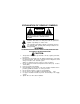
EXPLANATION OF GRAPHIC SYMBOLS CAUTION RISK OF ELECTRIC SHOCK DO NOT OPEN CAUTION: TO REDUCE THE RISK OF ELECTRIC SHOCK DO NOT REMOVE COVER (OR BACK) NO SERVICEABLE PARTS INSIDE REFER SERVICING TO QUALIFIED SERVICE PERSONNEL The lightning flash with the arrowhead within a triangle is intended to alert tell the user that parts inside the product are capable of producing an electric shock .
SYSTEM OVERVIEW The LCM5043NP is comprised of a 5" Thin Film Transistor (TFT) Liquid Crystal Display ( LCD) Monitor. The LCM5643NP is comprised of a 5.6" Thin Film Transistor (TFT) Liquid Crystal Display ( LCD) Monitor. The Monitor for both of these systems have a 4:3 Aspect Ratio display that allows the user to select between two video sources (Not Supplied). The Monitors displays all functions with the comprehensive On Screen Display (OSD). Can be used with an optional Wired Headphone.
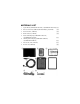
MATERIALS LIST 1. System Monitor (LCM5043NP=136C2187) or (LCM5643NP=136C2186) (1pc.) 2. Remote Control Unit (136B2156) with Lithium Battery, 3V,CR 2025 (1pc.) 3. Interconnect Box (136B2183) (1pc.) 4. Monitor Cable, 8' (112B3152) (1pc.) 5. Headrest Mounting Tray (LCM5043NP=102C3740) or (LCM5643NP=102C3742) 6. 7. 8. (1pc.) Trim Ring for Mounting Tray (LCM5043NP=102B3741) or (LCM5643NP=102B3743) (1pc.) Power Cable, 2.46' (112B3127) Removal Tool (108B3632) (1pc.) (1pc.
VEHICLE PREPARATION 1) 2) 3) 4) 5) 6) 7) 8) 9) Decide on the system configuration and the options that will be installed (i.e. what components, VCP, DVD, TV Tuner, Video Game, Monitor, FM Modulator, etc.). Read the manuals and get familiar with the electrical requirements and connections. Decide on the mounting locations and methods of mounting the products.
10) After verifying the proper operation of the system, proceed to mount each component. 11) The mounting method, and the location will vary from vehicle to vehicle, so this manual will only focus for the installation of the 12) The best location for the system components is: a) Monitor: Headrest or bracket (optional) mounted onto a flat surface. b) System Interconnection Box (AVX-6869): In line with all the system cabling and in an area were it can be easily accessed.
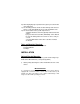
2) Slide monitor onto Surface Mount Bracket and then tighten the fasten wheel. Monitor Fastener Wheel Surface Mount Fastener Mounting Bracket 3) Adjust viewing angle of monitor by tightening the fastener at the side. Surface Mount 4) When the system components are mounted, test the system to verify that it is functioning correctly. Make sure that no wiring was pinched, or connected improperly during the final installation.
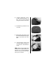
Headrest Mounting: 1) Remove the headrest from the vehicle for easiest installation. 2) Lay headrest on a flat surface. 3) Center trim collar on headrest as shown. NOTE: Depending on the angle of the headrest the Trim Ring and housing may be mounted upside down. 4) Using a Permanent Marker, mark headrest material along the interior of the Trim Ring. 5) Remove the Trim Ring and mark an “X” from corner to corner as shown.
6) Using the utility knife, cut the headrest material along the “X” lines. Do not cut the material along the other lines at this time. 7) This will leave you with an “X” cut as shown. 8) Pull the flaps up and cut the foam beneath the material to the proper depth. Cut all four sides of the foam. 9) Using your fingers, tear the foam out of the headrest leaving a recess where the shell will be inserted. NOTE: At this point you will need to install the harness up through the area into the recess.
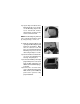
) Lay the flaps of headrest material down into the recess and insert the Mounting Tray into the recess. Check for fit. If it does not fit properly, you may need to remove some more foam. NOTE: The Mounting Tray will need to be secured to the headrest, either by using tie straps, screws, ect.. 11) Guide the cable through the side opening of the Mounting Tray and plug it into the Monitor. Make sure the connector locks into place.
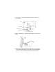
ELECTRICAL CONNECTION (Wiring Diagram) AV Output Video Source Input (1&2) Not Used 10
Monitor Removal: The following procedure is to remove the Monitor from the Mounting Tray using the supplied Removal Tool. NOTE: Use care when performing this procedure not to scratch any exposed surfaces with the edges of the Removal Tool. Masking tape applied to the two tips or legs of the Removal Tool will help prevent scratching. 1) Locate the Removal Tool and apply tape to the tips.
CONTROLS AND INDICATORS Headphone OPERATION 1. Press power On/Off button to the On position. The LED power indicator will light red. 2. Press the Picture Select button to adjust the picture display characteristics. The adjustments will be shown on the On Screen Display in the following sequence: Contrast, Brightness, Color, and TINT. 3. While in the video adjustment mode, press the up button to increase the selected adjustment level or press the down button to decrease the level.
MAINTENANCE To avoid electrical shock, do not open the enclosure. High voltage is present. No user serviceable parts inside the enclosure. Do not use any chemical solvent, cleaning agent or corrosive detergent to clean away dirt on the surface of the screen. To clean off dirt or fingerprint, we recommend the use of a soft damp lens cleaning cloth. Should there be requirement to replace blown fuse, do remember to disconnect all power supply and switched off the unit before replacing it with a new one.
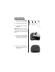
REMOTE CONTROLLER NOTE: The Remote Controller supplied with this system is a standard remote control, which is used to operate other systems. The Remote Controller is not a universal remote and will only perform the functions described herein. Only the Keys highlighted on the Remote Controller image bellow are used to operate this system.
MENU FUNCTION KEY: The MENU Key is used to navigate between the Color, Brightness and Tint adjustment modes. When the MENU Key is pressed an On Screen Display(OSD) will appear as shown bellow. OSD Press release and tap the MENU Key until the desired adjustment mode is selected. To return to the original settings select the RESET. When an adjustment mode is selected, press and hold the either the p or q (CH/DISK/SET) Key until the desired setting is reached.
VIDEO SOURCE MODE KEY: To switch between Video Input Sources (AV1 and AV2) press and release the MODE Key. NOTE: For the LCM5643NP - Select either *NTSC or PAL, press the p or q Keys (CH/DISK/SET). VOLUME CONTROL KEY: To increase or decrease the Volume, press and hold the VOL p or q Key until the desired volume is reached.
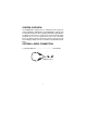
Replacement of Remote Controller Battery: 1. Use a small coin to pry open battery holder from compartment. 2. Remove old battery and put in a new one with positive sign “ + “ facing upward. 3. Push compartment into position. Precaution: 1. Dispose off used battery properly. 2. Do not misuse battery by short - circuiting the “ + “ and “ - “ terminal or put it into fire. 3. Remove used battery from compartment to prevent leakage from damaged battery. 4.
SPECIFICATIONS LCM5043NP: LCD Panel Size (Diagonal) ................................... LCD Panel Format ................................................. LCD Panel Resolution ........................................... LCD Backlight Life ................................................. Image Aspect Ratio ............................................... Video Input Signal .................................................. Power Source .......................................................
36 MONTH LIMITED WARRANTY Applies to Audiovox Mobile Video Products AUDIOVOX ELECTRONICS CORP. (the Company) warrants to the original retail purchaser of this product that should this product or any part thereof, under normal use and conditions, be proven defective in material or workmanship within 36 months from the date of original purchase, such defect(s) will be repaired or replaced with reconditioned product (at the Company's option) without charge for parts and repair labor.