
Installation manual

128-9300
13 of 24
13
Resistive Circuits, Multiplex Circuits As Well As 4 Wire Polarity Reversal and 5 Wire
Alternating 12 Volt Door Lock Control Circuits
These applications require the use of additional components which may include relays, xed resistor, a
door lock interface, or a data module. You can search the vehicle @ www.avxtech1.com, www.Flash-It.
com for vehcile specic information, or contact our tech service line or web site for additional information.
Additional Harnesses And Connectors For The System
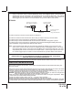
4 Pin Upgrade Telematic Module: (Connector Port)
Red = + 5 Volts / Black = Ground / White = Data TX / Yellow = Data RX
Connect the 4 pin harness found in the Telematic one way or Carlink II kits to the mating port on the con-
trolling circuit.
NOTE: If using the TWO WAY Telematic module, only Ground, TX, and RX are used on this port, the + 12
volt supply for the two way module must be sourced separately or the unit will not operate.
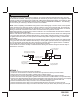
6 Pin 5 Wire Antenna/Receiver Program Push-Button Switch/LED Connector: Part # 1124296
Plug the previously routed antenna connector from the antenna receiver assemble into the mating connector
of the control module. This connector supplies 5 volts, ground and RF data input, LED cathode, and Valet
Enable to and from the antenna receiver and the remote start module. Be certain this connector is rmly
seated making good contact to the control unit.