
Installation Manual


128-9306
15 of 32
15
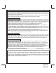
4 Pin Additional Harness: Parking Light Flasher I/O Siren & Ground Part # 1284301
1 Black: Chassis Ground
Connect the Black wire to a known vehicle ground source or to a solid clean metal part of the chassis.
Be certain to remove any paint or grease and secure this wire with a self tapping screw and ring terminal.
2 White w/ Red trace Wire: Parking Light Relay Input Wire
This wire is the common contact of the on board parking light asher relay. If the vehicle you are working
on has +12 volt switched parking lights, connect this wire to a fused + 12 volt source. (Max. 15 Amps)
NOTE: If the vehicle's parking lights are ground switched, connect this wire to chassis ground.
3 White w/ Black trace Wire: (+) Siren Output
This is the positive siren feed wire. Route this wire through a grommet in the rewall to the siren location.
Connect the White w/ Black Trace wire to the Red wire of the Siren. Secure the Black wire of the Siren
to a known chassis ground or solid clean metal surface.
4 White Wire: Parking Light Relay Output
This wire is the normally open contact of the on board parking light ash relay. Connect this wire to the
vehicle's parking light feed wire. This is the wire that gets switched on, either (+) or (-), when the vehicle's
parking light switch is activated.
Typical Vehicle Parking Lights
From Vehicle
Park Light Switch
White From
Remote Start Module
To + 12 Volts
(If Gnd. Switch See Note)
White/Red Wire From
Remote Start Module
15A