Model AA-RS5CS Installation Manual 3 Channel Remote Start / Keyless Entry System Installation Instructions This Unit Is Intended For Installation In Vehicles With 12 Volt Negative Ground Electrical Systems, Gasoline or Diesel With True Tach Reference And Automatic Transmissions Only.
The AA-RS5 Remote Start/Keyless Entry System is designed to be used with Automatic Transmission Vehicles Only! The unit provides wait to start input for glow plug pre-heat which will be used for all diesel applications. If this wire is not connected, then the unit will remain in the Gasoline mode setting which will crank the car when the RF signal is received with no delay.
IMPORTANT! DO NOT PLUG THE SIX PIN MAIN POWER HARNESS OR THE MULTI PIN INPUT / OUTPUT HARNESS INTO THE CONTROL MODULE UNTIL ALL CONNECTIONS TO THE VEHICLE HAVE BEEN MADE. AFTER SELECTING YOUR TARGET WIRES AS DEFINED BELOW, DISCONNECT THE NEGATIVE BATTERY CABLE FROM THE VEHICLE BATTERY PRIOR TO MAKING ANY CONNECTIONS.
SEE NEUTRAL START SAFETY TEST FOR FURTHER DETAILS. BLUE Wire: Ignition 1 Output Connect this wire to the ignition 1 wire from the ignition switch. This wire will show +12 volts when the ignition key is turned to the to the "ON" or "RUN" and the "START" or CRANK" positions, and will have 0 volts when the key is turned to the "OFF" and "ACCESSORY" positions. For Diesel Applications, this wire must be connected to the ignition circuit that powers the glow plugs if the vehicle requires glow plug pre-heating.
WIRING CONNECTIONS: 12 Pin Input / Output Harness Black Wire: Chassis Ground Source Connect the Black wire to a known vehicle ground source or to a solid clean metal part of the chassis. Be certain to remove any paint or grease and secure this wire with a self tapping screw and ring terminal. BLACK w/WHITE Tracer Wire: Control Switch The Black w/ White tracer wire provides ON-OFF control of the Remote Starter.
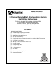
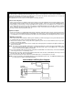
the Brown w/ Black trace wire to the output of the brake light switch. If the brake light switch in the vehicle switches ground, do not use the Brown w/ Black wire; see Grey w/ Black tracer wire. Brake Switch Positive Shutdown Detail YELLOW w/ BLACK Tracer Wire: + 12 Volt Alarm By - Pass Output NOTE: YOU MUST DISCONNECT THE IGNITION INPUT OF THE ALARM FROM ANY OTHER WIRE THAT IT IS PRESENTLY CONNECTED TO IN THE VEHICLE.
LIGHT BLUE Wire: Ignition 3 / Shock Disable Output This wire provides a 300mA ground output that becomes active 3 seconds before the Remote Start Unit initializes, and remains grounded while running plus an additional 4 seconds after the Remote Start Unit turns off. In all of the applications described below, a relay will be required. The Light Blue wire can be used to accommodate the following situations: A.
DARK GREEN Wire: Tach Sensor Input This wire will continually monitor the engine tach rate while the unit is under power of the Remote Start module. This wire will be routed to the vehicle ECM tach input or through the firewall into the engine compartment and connect to the negative side of the ignition coil. This Remote Start unit learns the tach rate of the vehicle and in most cases will operate properly from one multi coil pack regardless of the number of cylinders.
3 Wire Positive Switched Door Locks: In this application, the Red wire of the two pin harness provides a + 12 volt pulse during the disarming sequence, or pulsed 12 volt unlock output. Connect the Red wire to the low current 12 volt signal wire from the factory door unlock switch to the factory door unlock relay. The Green wire of the two pin harness provides a + 12 volt pulse during the arming sequence, or pulsed 12 volt lock output.
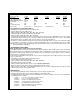
1. RF Programmable Features: Feature Selection 1 Run Time 2 Ign. 2 During Crank 3 Light Output During Run 4 Tach Mode 5 NA 6 Trouble Shooting 7 Door Locks 1 Flash 5 Min. Off Steady NA NA Off 1 Sec/1 Sec 2 Flash 10 Min. On Flash Tach NA On 3.5 Sec/3.5 Sec 3 Flash 15 Min. 4 Flash 20 Min. NA NA 1 Sec/Dbl 1 Sec Default 10 Min. On Steady Tach NA Off 1 Sec/1 Sec To program these selectable features: 1. 2. 3. 4. 5. 6. Start with the programming switch in the OFF position.
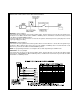
Multi Coil Pack Adaptor: (Optional) The multi coil pack adaptor, (P/N 136B1400), is designed for use with vehicles having multiple ignition coils where a single point tach signal is unavailable. To use the adaptor, the Green/Black wires must connect to the negative side of the ignition coil(s). 1. For vehicles utilizing independent coils per cylinder, connect the three Green/Black leads to alternate coils. To achieve optimum performance the coil signals must be evenly distributed.
DO NOT RELEASE THIS VEHICLE TO THE CONSUMER UNTIL YOU CONFIRM THE OPERATION OF THE MANUAL SHUT DOWN / ENABLE FEATURE. NEUTRAL START SAFETY TEST: The intent of the neutral start switch is to prevent the vehicle from starting while the gear selector is in any position other than Park, or Neutral. When installing a Remote Start Device, it is imperative that the Yellow Starter wire be connected to the ignition switch side of the Neutral Start Switch.
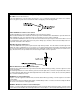
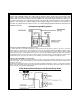
3. Connect the Anode, (Non Striped) end, of the diode to one side of the Remote Starts enable switch. 4. Connect the other side of the enable switch to the Black/White enable input wire of the Remote Start unit. The reference diagram below shows a typical GM B Body ECM reference wire and how it is to be connected to the Remote Start Unit. KEY IN SENSOR CIRCUITS: If the vehicle you are working on does not have or you cannot locate the ECM reference wire, there are two alternatives available.
METHOD 1 Circuits may be used only if the above circuit is not available. To connect to the key in sensor as shown in method 1: A. Locate the control wire that connects the drivers door pin switch to the key in sensor switch. B. Cut this wire and connect the ignition cylinder side to chassis ground. C. Locate the key in sensor switch wire that connects the chime module to the ignition cylinder . D. Cut this wire and connect the ignition cylinder side to terminal 30 of a P&B VF45F11 or equivalent relay. E.
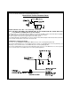
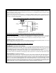
NOTE: A second 4002 series diode may be required to maintain the integrity of the hood open, shut down circuit. If this is the case, it must be installed as shown in the diagram above. The anode (Non Striped) side must be connected to the Gray/Black wire of the Remote Start Unit. The cathode (Striped) side must be connected to the hood pin switch.
WIRING DIAGRAM © 2000 Audiovox Electronics Corp.