Model AA-RS10CS Installation Manual 3 Channel Remote Start / Keyless Entry System Installation Instructions This Unit is Intended for Installation in Vehicles with 12 Volt Negative Ground Electrical Systems, Gasoline or Diesel with True Tach Reference and Automatic Transmissions Only.
The AA-RS10CS Remote Start/Keyless Entry System is designed to be used with Automatic Transmission Vehicles Only! The unit provides a selectable ignition control that allows a 10 second output for glow plug pre-heat which may be required for certain diesel vehicles, (see selectable feature #9). If the diesel engine has a instant fire, (no glow plug pre-heat system), feature #9 should remain in the default Gasoline mode setting.
WIRING THE 6 PIN MAIN POWER HARNESS: RED w/ WHITE Trace Wire: + 12 volt Battery 1 Source Connect this wire to a + 12 VDC constant source found at the vehicle's ignition switch using the 30 Amp fuse and holder provided. This wire provides power for the control circuit as well as the ignition 1 and ignition 2 relays.
BLUE Wire: Ignition 1 Output Connect this wire to the ignition 1 wire from the ignition switch. This wire will show +12 volts when the ignition key is turned to the to the "ON" or "RUN" and the "START" or CRANK" positions, and will have 0 volts when the key is turned to the "OFF" and "ACCESSORY" positions. For Diesel Applications, this wire must be connected to the ignition circuit that powers the glow plugs if the vehicle requires glow plug pre-heating.
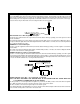
GREY Wire: Negative Inhibit Input 1 Connect the GREY wire to the previously mounted hood pin switch provided . This wire will be routed through the fire wall into the engine compartment. It is necessary to use an existing grommet when passing wires through the fire wall to prevent short circuiting. This is an important safety feature of APS 675, and failure to use this feature can result in serious injury. Route the wire to the pin switch and connect it using the bullet connector provided.
(2) WHITE Wires: Parking Light Flasher These wires are the COMMON and NORMALLY OPEN contacts of the on-board parking lamp relay. If the vehicle's parking lights are a +12 volt switched system, connect (1) of the White wires to a fused (15A max.) +12 volt battery source, and connect the second White wire to the vehicle's parking light wire.
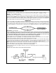
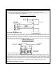
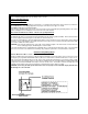
4. Cut (#1) wire (as shown), and connect the ignition switch side of the cut wire to terminal #87a of the relay. Connect the other side of the (#1) wire to terminal #30. 5. Connect the previously selected resistor from terminal #87 to the second (#2) wire (as shown). NOTE: The above information and following diagram is for the GM VATS system only. For GM PASS LOCK System you will require the Audiovox AS-PASS II Module.
In this application, the Red wire of the two pin harness provides a ground pulse during the arming sequence, or pulsed ground lock output. Connect the Red wire to the low current ground signal wire from the factory door lock switch to the factory door lock relay. The Green wire of the two pin harness provides a ground pulse during the disarming sequence, or pulsed ground unlock output.
Audiovox AS-9159 Door Lock Interface, (or equivalent 30 A automotive relays) must be used. Refer to the Audiovox Door Lock Wiring Supplement for proper wiring of these circuits. 4 Wire Polarity Reversal and 5 Wire Alternating 12 Volt Door Lock Control Circuits In these applications, the AS 9159 Door Lock Interface ( or equivalent 30 A automotive relays) must be used. Refer to the AUDIOVOX Door Lock Wiring Supplement for proper connection to these types of circuits.
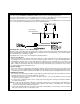
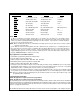
Feature Selection 1 Flash 2 Flashes Default First 1 Second Door Locks 3.5 Second Door Locks 1 Second Second 10 Minute Run Time 15 Minute Run Time 10 Minute Third Park Lights Steady On Park Lights Flash Steady Fourth (No Function) Tach Operation Tach Fifth (No Function) (No Function) ------------ Sixth Ign. 2 Off During Crank Ign.
and or single injector. To learn tach; 1. Start with the programming switch in the OFF position. 2. Turn the ignition key to the ON position. 3. Flip the program switch ON - OFF - ON - OFF - ON - then OFF. 4. Immediately turn the ignition key OFF. 5. Flip the program switch ON, then start the vehicle using the ignition key. 6. When the unit senses the tach signal, the parking lights will begin to flash. 7. Flip the program switch OFF.
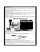
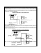
2. For vehicles utilizing 2 cylinder firing per coil pack, connect Green/Black to the tach side of each coil pack. For 8 cylinder, four coil systems, connect to any of the three coils. 3. Connect the Yellow wire to a +12 volt ignition 1 source. This wire will have +12 volts with the ignition in the on and start position and have 0 volts with the ignition in the off position. 4. Connect the Green wire to the (Green) or (Orange/Green) tach input of the Audiovox remote start unit.
4. Sitting in the vehicle, start the engine using the vehicle's ignition key. 5. Step on the brake pedal and shift the gear selector into reverse. 6. Allow the transmission to shift. When you feel the engine pull, do not move the gear selector just turn the ignition switch off. DO NOT attempt to remove the key. 7. Keeping the brake pedal depressed, activate the RF transmitter in an attempt to start the vehicle. The car should not start. 8.
KEY IN SENSOR CIRCUITS: If the vehicle you are working on does not have or you cannot locate the ECM reference wire, there are two alternatives available. Although not preferred, the vehicle Key In Sensor may be re-configured to allow a margin of safety and will prevent the vehicle with a Mechanical Neutral Start Switch from starting in gear. AUDIOVOX ADVISES THAT YOU MAINTAIN THE FACTORY CIRCUIT WHENEVER POSSIBLE. The following two circuits may be used only if the above circuit is not available.
Remote Start Unit as shown below. METHOD 2 To connect to the key in sensor circuit as shown for method 2: A. Locate the control wire that connects the drivers door pin switch to the key in sensor switch. B. Cut this wire and connect the ignition cylinder side to chassis ground. C. Locate the key in sensor switch wire that connects the chime module to the ignition cylinder . D.
WIRING DIAGRAM © 2000 Audiovox Electronics Corp.