
Speaker System User Manual

3
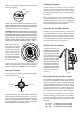
Tighten all four of the mounting screws in the same
manner until the speaker is properly aligned and held
tight to the ceiling surface.
Painting the Speaker
A paint shield is included in each ACLCR6C
speaker package. Place the paint shield inside the
frame to protect the speaker. You can now safely
paint the speaker frame to match your wall surface
if you desire.
When painting the grill caution should be taken to
ensure that paint does not clog or congest the
perforated openings in the grill. This would prevent
proper operation of the grill by restricting the airflow
from the individual drivers in the speaker.
Aiming the Tweeter
Carefully place your fingertips at the plastic edges
of the tweeter housing.
Removing the ACLCR6C Speaker
Should it ever become necessary to remove the
ACLCR6C speaker from the ceiling, simply remove the
grill and turn the four mounting screws counter-
clockwise until you feel the clamps lock out of position
in their resting flange. The speaker should easily come
out of the wall for service or replacement.
Press Here
Press Here
Press Here
Press Here
Caution: Do not over tighten!
Recommended Speaker Wire Gauges
The resistance of the speaker wire in your installation
can cause your speakers to perform at less than their
optimum quality level. Excess resistance caused by
using undersized speaker wire can result in loss of
detail and definition in the bass region of your audio
program as well as loss of dynamic range. Over
extremely long wire runs you may even experience a
loss of high frequency content in the audio signal.
50’ or less - 16 Gauge 2-Cond. CL3 Rated
50’ - 150’ - 12 Gauge 2-Cond. CL3 Rated
150’ - 200’ - 10 Gauge 2-Cond. CL3 Rated
To prevent sonic degradation in your ACLCR6C
speaker installation, total speaker wire resistance
should be kept below 0.5 ohms. The following table
lists recommended speaker wire gauge versus wire
run length.
Using gentle pressure, swivel the tweeter to aim the axis
of the tweeter toward the listening area. You can use a
piece of music with a solid center-imaged vocalist to
assist in correctly aiming the tweeter. When the tweeters
are properly aligned, you will hear a coherent and stable
center image from your listening position.
Next make sure that the clamps are positioned inside
frame of the speaker.
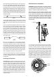
With the grill removed, place the speaker in the ceiling
opening. Make sure that the speaker wire is not hanging
against the speaker where it can vibrate and rattle as the
speaker reproduces your audio program.
Next, one at a time, turn
each of the four screws
that operate the clamps
counter clockwise a few
turns until you feel the
clamp is loose from its
resting position. Now turn
the screw clockwise until
you feel the clamp contact
the ceiling surface.
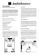
Locate a small hook tool
(available at most auto parts
stores or home improvement
shops, resembling a dentist’s
pick- a bent paper clip or
stiff wire will work as well),
hook the metal mesh of the
grill near a corner or edge
and gently pull it towards you.
Only lift the grill 1/4" (6mm) at
this location. Move the tool
1-2" (25-50mm) and repeat
until the grill can be removed
w i t h o u t d a m a g i n g i t
(Figure 7).
Grill Removal (if installed)
Figure 7
Clamp
Frame
Installation Tip! Note that the speaker is set in the frame
at an angle so that the cone can be directed toward
the listening position. Ensure the cone of the speaker is
angled toward the listening position before proceeding
to the next step. This is easily done by rotating the
speaker until the optimum angle is achieved, typically
a direct line of sight to
the listener (Figures 1 and 2).
1
2
3
4