Installation Manual Version 6.
Installation Manual Contents Table of Contents 1 Introduction....................................................................................................... 11 2 Installing the Device ......................................................................................... 13 2.1 Installing the MP-11x Series ...................................................................................13 2.1.1 2.1.2 2.1.3 2.1.4 2.2 Installing MP-124 .....................................................
MediaPack Series 4 Monitoring the Device ...................................................................................... 55 4.1 Front-Panel LEDs ...................................................................................................55 4.2 Web Interface .........................................................................................................56 4.2.1 4.2.2 Installation Manual Viewing Alarms ..............................................................................
Installation Manual Contents List of Figures Figure 1-1: Required Steps to Install the Device ................................................................................... 11 Figure 2-1: MP-11x (e.g., MP-118) Front Panel .................................................................................... 13 Figure 2-2: MP-11x (e.g., MP-118) Rear Panel Connectors ................................................................. 14 Figure 2-3: View of MP-11x Underside .................................
MediaPack Series List of Tables Table 2-1: MP-11x Rear Panel Component Descriptions...................................................................... 14 Table 2-2: Mounting Components on MP-11x Underside ..................................................................... 15 Table 2-3: MP-11x Rack Mount ............................................................................................................. 17 Table 2-4: Reset Button Description on MP-124 Front Panel ..............................
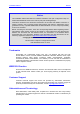
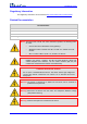
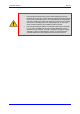
Installation Manual Notices Notice This Installation Manual describes the hardware installation and quick configuration setup for AudioCodes MediaPack series Voice-over-IP (VoIP) SIP media gateways. Information contained in this document is believed to be accurate and reliable at the time of printing. However, due to ongoing product improvements and revisions, AudioCodes cannot guarantee accuracy of printed material after the Date Published nor can it accept responsibility for errors or omissions.
MediaPack Series Regulatory Information The Regulatory Information can be viewed at http://www.audiocodes.com/downloads. Related Documentation Document Name Product Reference Manual MP-11x & MP-124 SIP Release Notes MP-11x & MP-124 SIP User's Manual CPE Configuration Guide for IP Voice Mail Notes: Throughout this manual and unless otherwise specified, the following terms are used: • Device refers to the MediaPack series gateways.
Installation Manual Notices Notes: Version 6.0 • FXO (Foreign Exchange Office) is the interface replacing the analog telephone and connects to a Public Switched Telephone Network (PSTN) line from the Central Office (CO) or to a Private Branch Exchange (PBX). The FXO is designed to receive line voltage and ringing current, supplied from the CO or the PBX (just like an analog telephone). An FXO VoIP device interfaces between the CO/PBX line and the Internet.
MediaPack Series Reader’s Notes Installation Manual 10 Document #: LTRT-59811
Installation Manual 1 1. Introduction Introduction This manual provides you with step-by-step procedures for initial and basic setup of the device, including hardware installation and software configuration. The flowchart below summarizes these steps: Figure 1-1: Required Steps to Install the Device Notes: Version 6.0 • For detailed information on how to fully configure the device, refer to the device's User’s Manual. • Prior knowledge of IP networking is recommended.
MediaPack Series Reader’s Notes Installation Manual 12 Document #: LTRT-59811
Installation Manual 2 2. Installing the Device Installing the Device This section describes the MP-11x (refer to 'Installing the MP-11x Series' on page 13) and MP-124 (refer to 'Installing MP-124' on page 21) hardware installation. This includes physical description, unpacking the shipped package, and mounting and cabling procedures. 2.1 Installing the MP-11x Series This subsection describes the MP-11x hardware installation. 2.1.
MediaPack Series 2.1.1.2 MP-11x Rear Panel The device's rear panel provides the ports for cabling the device to the various interfaces. The figure below displays the rear panel of the MP-118 device (as an example). Figure 2-2: MP-11x (e.g., MP-118) Rear Panel Connectors The following table describes the MP-11x rear panel ports: Table 2-1: MP-11x Rear Panel Component Descriptions Item # Label 1 100-240~0.3A max. 2 Ethernet 3 RS-232 4 FXS and/or FXO Component Description AC power supply socket.
Installation Manual 4. 2.1.3 2. Installing the Device Ensure that in addition to the MP-11x unit, the package contains the following items: • AC power cable. • Small plastic bag containing four anti-slide bumpers for desktop installation. • Regulatory Information document. 5. Check, retain, and process any documents. 6. Notify AudioCodes or your local supplier of any damage or discrepancies.
MediaPack Series 2.1.3.1 Desktop Mounting Attach the four (supplied) anti-slide bumpers to the base of the MP-11x and place it on a desktop in the desired position. 2.1.3.2 Wall Mounting Follow the procedure below for mounting the MP-11x on a wall. ¾ To mount the MP-11x on a wall: 1. 2.1.3.3 Drill four holes according to the following dimensions: • Horizontal distance between holes: 140 mm (5.51 inches) • Vertical distance between: 101.4 mm (4 inches) 2.
Installation Manual 3. 2. Installing the Device Attach the shelf to the rack using four standard rack screws (not supplied). Figure 2-5: MP-11x Rack Mount Table 2-3: MP-11x Rack Mount Item # Functionality 1 Standard rack holes used to attach the shelf to the rack. 2 Eight shelf-to-device screws. 2.1.4 Cabling the MP-11x This section describes the MP-11x cabling procedures: ¾ To cable the MP-11x: Connecting to the Ethernet network (refer to 'Connecting MP-11x to the Network' on page 18).
MediaPack Series 2.1.4.1 Connecting MP-11x to the Network Follow the procedure below for connecting MP-11x directly to the Ethernet network. ¾ To connect MP-11x directly to the Ethernet network: Using a crossover Ethernet cable with RJ-45 connectors on either end, connect the MP-11x Ethernet port (labeled Ethernet), directly to the network.
Installation Manual 2.1.4.3 2. Installing the Device Cabling the FXS Lifeline The Lifeline provides a wired analog POTS phone connection to any PSTN or PBX FXS port when there is no power or when the network connection fails. Therefore, you can use the Lifeline phone even when MP-11x is not powered or not connected to the network.
MediaPack Series ¾ To cable the combined MP-11x FXS/FXO Lifeline: 1. Connect a fax machine, modem, or phone to each of the FXS ports. 2. Connect an analog PSTN line to each of the FXO ports. Figure 2-10: Lifeline Cabling for FXS and FXO Devices 2.1.4.4 Connecting MP-11x RS-232 Port to a PC Follow the procedure below to connect the MP-11x serial (RS-232) interface to a PC using a straight-through, PS/2 to DB-9 cable adaptor.
Installation Manual 2. Installing the Device ¾ To connect MP-11x to a PC: 1. Connect the PS/2 connector (refer to the figure below for connector pinouts) on one end of the cable to the MP-11x RS-232 port (labeled RS-232). 2. Connect the DB-9 connector at the other end of the cable to either the COM1 or COM2 RS-232 communication port on your PC.
MediaPack Series 2.2 Installing MP-124 This subsection describes the MP-124 hardware installation. 2.2.1 Physical Description The subsections below provide a physical description of the MP-124 front and rear panels. 2.2.1.1 MP-124 Front Panel The MP-124 front panel (shown in the figure below) provides LEDs for indicating various operating statuses. In addition, the front panel provides a reset button, described in the table below.
Installation Manual 2.2.1.2 2. Installing the Device MP-124 Rear Panel The device's rear panel (shown in the figure below) provides the ports for cabling the device to the various interfaces. Figure 2-14: MP-124 Rear Panel - AC Power Model Figure 2-15: MP-124 Rear Panel - DC Power Model The table below describes the MP-124 rear panel components. Table 2-5: MP-124 Rear Panel Component Descriptions Item # Label Component Description Protective earthing screw (mandatory for all installations).
MediaPack Series 2.2.2 Unpacking and Checking Package Contents Follow the procedure below for unpacking the carton in which the MP-124 is shipped. ¾ To unpack the MP-124: 2.2.3 1. Open the carton and remove packing materials. 2. Remove the MP-124 unit from the carton. 3. Check that there is no equipment damage. 4.
Installation Manual 2.2.3.2 2. Installing the Device 19-inch Rack Mounting The MP-124 can be installed in a standard 19-inch rack, by using two short, equal-length brackets (supplied). The MP-124 with attached brackets for rack installation is shown in the figure below: Figure 2-17: MP-124 with Brackets for Rack Installation Rack Mount Safety Instructions When installing the chassis in a rack, implement the following safety instructions: Version 6.
MediaPack Series ¾ To install the MP-124 in a 19-inch rack: 2.2.4 1. Remove the two screws located on one side of the MP-124 (nearest the front panel). 2. Insert the peg on one of the brackets into the third air vent down on the column of air vents nearest the front panel. 3. Swivel the bracket until the holes in the bracket align with the two empty screw holes on the MP-124. 4. Use the supplied screws to attach the bracket to the side of the MP-124. 5.
Installation Manual 2.2.4.1 2. Installing the Device Power Surge Protection and Grounding of MP-124 This section discusses power surge protection and grounding of MP-124. Warning: • Ensure that you connect MP-124 to an electrical socket outlet that provides protective earthing (grounding). Prior to connecting power, refer to the Regulatory Information provided in the User’s Manual.
MediaPack Series The MP-124 chassis is equipped with a protective earthing screw. Ensure that you connect this to the grounding point using a suitable wire. Fasten the cable securely using a 6-32 UNC screw. Note: Proper grounding is crucial to ensure the effectiveness of the primary protection devices against power surges.
Installation Manual 2.2.4.2 2. Installing the Device Connecting MP-124 to the Ethernet Network Follow the procedure below for connecting MP-124 directly to the Ethernet network. ¾ To connect MP-124 directly to the Ethernet network: Using a crossover Ethernet cable with RJ-45 connectors on either end, connect the MP-124 Ethernet port (labeled ETHERNET), directly to the network.
MediaPack Series 2.2.4.3 Connecting MP-124 to FXS Interface The MP-124 interfaces with the analog telephone interfaces by connecting to a main distribution frame (MDF), using a 50-pin Telco cable. MP-124 Safety Notice To protect against electrical shock and fire, use a 26 AWG min wire to connect analog FXS lines to the 50-pin Telco connector. Warning: To reduce noise interference, use a twisted pair Octopus cable that is terminated on a metal-hooded 50-pin Telco connector.
Installation Manual 2. Installing the Device 4. Insert and fasten the male connector to the female 50-pin Telco connector on the MP-124 rear panel (labeled Analog FXS Lines 1-24). 5. Connect the telephone lines from the MDF adaptor block to a fax machine, modem, or telephones by inserting each RJ-11 connector on the 2-wire line cords of the POTS phones into the RJ-11 sockets on the front of an MDF adaptor block, as shown in the figure below.
MediaPack Series 2.2.4.4 Connecting MP-124 RS-232 Port to a PC Follow the procedure below to connect the MP-124 serial (RS-232) interface to a PC using a standard, straight-through cable with DB-9 connectors on either end. ¾ To connect MP-124 to a PC: 1. Connect the DB-9 connector (refer to the figure below for connector pinouts) on one end of the cable to the MP-124 RS-232 port (labeled RS-232). 2.
Installation Manual 2.2.4.5 2. Installing the Device Connecting MP-124 to Power The MP-124 can be powered either from a standard AC electrical outlet or a 48-VDC power supply. The power configuration depends on the ordered MP-124 model. 2.2.4.5.1 AC Power Supply This section describes cabling of the MP-124 model for AC power. Warnings: • The device must be connected only by professional service personnel.
MediaPack Series ¾ To connect MP-124 to a DC power supply: 1. Insert two 18 AWG wires into the supplied DC terminal block (ensure correct polarity), and then fasten the two screws located directly above each wire block. 2. Insert the DC terminal block into the DC inlet on the MP-124 rear panel, and then secure it to the device by fastening the two adaptor-to-panel screws located on the terminal block. Figure 2-23: Wired DC Power Terminal Block Connected to MP-124 Legend: 3. 1.
Installation Manual 3 3. Configuring the Device Configuring the Device This section describes initial, basic setup configuration for the device, using the device's embedded Web server (Web interface). Notes: 3.1 • The device is supplied with application software (cmp file) already residing on its flash memory. This software is set to factory defaults. • If necessary, you can restore the device to factory defaults (refer to 'Restoring Factory Default Settings' on page 48).
MediaPack Series 3.1.1 Assigning an IP Address Using HTTP You can assign an IP address to the device, using the device's Web interface. ¾ To assign an IP address using HTTP: 1. Disconnect the device from the network and reconnect it to a PC using one of the following methods: • Using a hub or switch between a PC and the device: Connect the network interface on your PC to a port on a network hub / switch, using a standard Ethernet cable.
Installation Manual 4. 3.1.2 3. Configuring the Device Change the device's IP address, by performing the following: a. Open the ‘Multiple Interface Table’ page, (Configuration tab > Network Settings menu > IP Settings). b. Define the device's IP address, subnet mask, and default Gateway IP address (for “OAMP + Media + Control” application type) so that they correspond to your network IP scheme. c. Click Apply. d.
MediaPack Series 8. In the ‘Gateway’ field, enter the IP address of the default gateway (if any). 9. Click Apply to save the new client. 10. Click OK; the ‘Client Configuration’ screen closes. 11. Physically reset the device using the hardware reset button (or power down and then power up the device). This causes the device to use BootP; the device changes its network parameters to the values provided by BootP. Figure 3-2: BootP Client Configuration Screen 3.1.
Installation Manual 6. 3. Configuring the Device b. Press the # key. c. Dial the new subnet mask (e.g., 255*255*0*0), and then press # to finish. d. Review the new subnet mask, and then press 1 to save. To change the default Gateway IP address: a. Press 3 followed by the # key; The current default Gateway address is played. b. Press the # key. c. Dial the new default Gateway address (e.g., 192*168*0*1), and then press # to finish. d.
MediaPack Series c. 8. Press the selected pattern code, and then press # to finish. Press 1 to save, and then hang up the handset. The device retrieves the configuration from the HTTP server. The following is an example perl CGI script, suitable for most Apache-based HTTP servers for generating configuration dynamically per pattern #6 above. Copy this script to /var/www/cgi-bin/acconfig.
Installation Manual 3.1.4 3. Configuring the Device Assigning an IP Address Using the CLI You can assign an IP address to the device, using command-line interface (CLI). Note: The CLI method for assigning an IP address is not applicable to MP-112 as this model does not provide RS-232 serial interface. ¾ To assign an IP address via the CLI: 1.
MediaPack Series 3.2 Configuring Basic SIP Parameters Once you have completed the previous sections, you are ready to start configuring the device using the Web interface. For information on how to fully configure the device, refer to the device's User’s Manuals. Tip: Once the device is configured, backup your settings by saving the configuration (ini) file to your PC.
Installation Manual 3.2.1 3. Configuring the Device Enabling Channels and Configuring Call Routing (Example) This section provides an example for enabling the device's channels and for configuring Tel (PSTN)-to-IP call routing. This includes assigning the channels a telephone number and then routing calls (e.g., of dialed numbers with prefix 10) from these channels to a specific IP destination (e.g., IP address 10.33.24.14). ¾ To enable channels and configure call routing: 1.
MediaPack Series The figure below shows an example of a configuration setup of two communicating FXS devices. Phones ‘101’ and '102' are connected to the first two channels of device with IP address 10.33.24.18; phone ‘120’ is connected to the first channel of device 10.33.24.14. The configuration in the 'Endpoint Phone Number Table' and ‘Tel to IP Routing Table’ pages (refer to the figure below) enables calls to be made between these two devices as well as between phones connected to the same device.
Installation Manual 3.3 3. Configuring the Device Saving and Resetting the Device To apply configuration changes to the device's volatile memory (RAM), click the Submit button located on the page in which you are configuring. Modifications to parameters with on-the-fly capabilities are immediately applied to the device; other parameters are applied only after a device reset.
MediaPack Series 3.4 Changing Login User Name and Password To prevent unauthorized access to the Web interface, two Web user accounts (login accounts) are available (primary and secondary) with assigned user name and password. For detailed information on the Web user accounts, refer to the device's User’s Manual.
Installation Manual 3.5 3. Configuring the Device Backing Up and Restoring Configuration You can save a copy/backup of the device's current configuration settings as an ini file to a folder on your PC, using the 'Configuration File' page. The saved ini file includes only parameters that were modified and parameters with other than default values. The 'Configuration File' page also allows you to load an ini file to the device.
MediaPack Series ¾ To load (or restore) the ini file: 3.6 1. Click the Browse button, navigate to the folder in which the ini file is located, select the file, and then click Open; the name and path of the file appear in the field beside the Browse button. 2. Click the Load INI File button, and then at the prompt, click OK; the device uploads the ini file and then resets (from the cmp version stored on the flash memory).
Installation Manual 3.7 3. Configuring the Device Upgrading the Device You can upgrade the device with the following files, using the device's Web interface: Firmware (cmp) file using the Web interface's Software Update Wizard (refer to 'Software Upgrade Wizard' on page 49). Auxiliary and ini files using the 'Load Auxiliary Files' page (refer to 'Upgrading the ini and Auxiliary Files' on page 52).
MediaPack Series ¾ To use the Software Upgrade Wizard: 1. Stop all traffic on the device (refer to the note above). 2. Open the 'Software Upgrade Wizard' (Management tab > Software Update menu > Software Upgrade Wizard); the 'Software Upgrade Wizard' page appears. Figure 3-9: Start Software Upgrade Wizard Screen 3. Click the Start Software Upgrade button; the 'Load a CMP file' Wizard page appears.
Installation Manual 3. Configuring the Device Note: At this stage, you can quit the Software Update Wizard, by clicking Cancel , without requiring a device reset. However, once you start uploading a cmp file, the process must be completed with a device reset. 4. Click the Browse button, navigate to the cmp file, and then click Send File; the cmp file is loaded to the device and you're notified as to a successful loading. 5.
MediaPack Series 10. Click End Process to close the wizard, and then in the 'Enter Network Password' dialog box, enter your login user name and password (described in Accessing the Web Interface) and click OK; a message box appears informing you of the new CMP file. 11. Click OK; the Web interface now becomes active and reflecting the upgraded device. 3.7.
Installation Manual 3. Configuring the Device ¾ To load an auxiliary file to the device: 1. Open the 'Load Auxiliary Files' page (Management tab > Software Update menu > Load Auxiliary Files). Figure 3-12: Load Auxiliary Files Page 2. Click the Browse button corresponding to the file type that you want to load, navigate to the folder in which the file is located, and then click Open; the name and path of the file appear in the field next to the Browse button. 3.
MediaPack Series Reader’s Notes Installation Manual 54 Document #: LTRT-59811
Installation Manual 4 4. Monitoring the Device Monitoring the Device The operating status of the device can be monitored in the following ways: 4.1 Monitoring the device's hardware front-panel LEDs (refer to 'Front-Panel LEDs' on page 55). Monitoring the device using the Web interface (refer to 'Web Interface' on page 56).
MediaPack Series Label Type Color State Data Packet Status Green Blinking Transmitting RTP packets. Red Blinking Receiving RTP packets. - - Green On Off-hook or ringing. Red On Line malfunction. - - Telephone Interface Channels 4.2 Function No traffic. Normal.
Installation Manual 4.2.2 4. Monitoring the Device Viewing Channel Status The 'Home' page displays channel port icons that indicate the voice channels' operating status. You can use these port icons to drill down to view detailed channel status. For a detailed description of the 'Home' page, refer to the device's User's Manual.
Installation Manual Version 6.0 www.audiocodes.