
Installation manual

Version 6.2 27 February 2011
Installation Manual 2. Installing the Device
MP-124 must be installed in the Telecommunication rack. MP-124 grounding screw must
be connected to the equipotential grounding bus bar located in the Telecommunication
rack, using a wire of 6mm
2
surface wire. This line must be connected to the equipotential
bus bar of the electrical circuit board located in the Telecommunication room, using a
stranded cable with surface area of 25 mm
2
. The length of this cable must be as short as
possible; no longer than 3 meters.
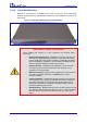
The MP-124 chassis is equipped with a protective earthing screw. Ensure that you connect
this to the grounding point using a suitable wire. Fasten the cable securely using a 6-32
UNC screw.
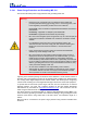
Note: Proper grounding is crucial to ensure the effectiveness of the primary protection
devices against power surges. Therefore, both the primary protector and MP-124 must be
connected to the equipotential ground bus (in electrical switch board) that is connected
directly to the grounding of the foundation reinforcement conductor.
Before installation, loop-testing grounding measurements must be done by a certified
electrician to verify the quality of the grounding connection. The grounding impedance must
not exceed 0.5 ohm.
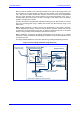
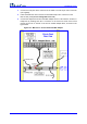
The figure below illustrates the connection method for grounding and lightning protector.
Figure 2-18: Grounding and Power Surge Protection
Telephone Lines
Outside Building
Main Distribution Frame (MDF)
To Foundation
Reinforcement/Ring Conductor (Ground)
Tip
Ring
26 AWG
MP-124
Equipment Rack
Telecommunication Room
MP-124
Stranded
Wire
10 mm
2
50-Pin Telco for
Telephone Lines
Stranded Wire
6 mm
2
Equipotential
Ground Bus Bar
Primary Lightning
Protection (CIRCA)
Equipotential Ground Bus
in Electrical Board