
Installation manual

Version 6.2 25 February 2011
Installation Manual 2. Installing the Device
¾ To install MP-124 in a 19-inch rack:
1. Remove the two screws located on one side of MP-124 (nearest the front panel).
2. Insert the peg on one of the brackets into the third air vent down on the column of air
vents nearest the front panel.
3. Swivel the bracket until the holes in the bracket align with the two empty screw holes
on MP-124.
4. Use the supplied screws to attach the bracket to the side of MP-124.
5. Repeat steps 1 through 4 to attach the second bracket to the other side of MP-124.
6. Position MP-124 in the rack and line up the bracket holes with the rack frame holes.
7. Use four standard rack screws (not supplied) to attach MP-124 to the rack.
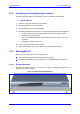
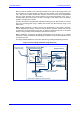
2.2.4 Cabling MP-124
This section describes the MP-124 cabling procedures:
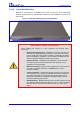
Grounding (earthing) MP-124 (refer to 'Grounding MP-124' on page 25).
Connecting to the Ethernet network (refer to 'Connecting MP-124 to the Ethernet
Network' on page 27).
Con
necting to FXS analog lines (refer to 'Connecting MP-124 to FXS Interface' on
page 28).
Serial connection to a computer (refer to 'Connecting MP-124 RS-232 Port to a PC' on
page 30).
Connecting to the power supply (refer to 'Connecting MP-124 to Power' on page 31).
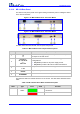
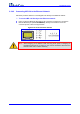
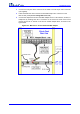
Once you have completed the above hardware installation steps and after powering-up MP-
124, the Ready and LAN LEDs on the front panel light up green (after a self-testing period
of about a minute). Any malfunction in the startup procedure changes the Ready LED to
red (for details on the MP-124 LEDs, refer to 'Monitoring Front-Panel LEDs' on page 55).
Once you have cabled the device, you can begin configuring the device (refer to
'Configuring the Device' on page 35).