MediaPackTM Series Analog VoIP Gateways MP‐11x & MP‐124 Installation Manual Version 6.
Installation Manual Contents Table of Contents 1 Introduction......................................................................................................... 9 2 Installing the Device ......................................................................................... 11 2.1 Installing MP-11x ....................................................................................................11 2.1.1 2.1.2 2.1.3 2.1.4 2.2 Installing MP-124 ..............................................
MediaPack Series 4 Monitoring the Device ...................................................................................... 55 4.1 Front-Panel LEDs ...................................................................................................55 4.2 Web Interface .........................................................................................................56 4.2.1 4.2.2 Installation Manual Viewing Alarms ..............................................................................
Installation Manual Contents List of Figures Figure 1-1: Required Steps to Install the Device ..................................................................................... 9 Figure 2-1: MP-11x (e.g., MP-118) Front Panel .................................................................................... 11 Figure 2-2: MP-11x (e.g., MP-118) Rear Panel ..................................................................................... 12 Figure 2-3: View of MP-11x Underside .......................
MediaPack Series List of Tables Table 2-1: MP-11x Rear Panel Component Descriptions...................................................................... 12 Table 2-2: Mounting Components on MP-11x Underside ..................................................................... 13 Table 2-3: MP-11x Rack Mount ............................................................................................................. 15 Table 2-4: Reset Button Description on MP-124 Front Panel ..............................
Installation Manual Notices Notice This Installation Manual describes the hardware installation and quick configuration setup for AudioCodes MediaPack series Voice-over-IP (VoIP) SIP media gateways. Information contained in this document is believed to be accurate and reliable at the time of printing. However, due to ongoing product improvements and revisions, AudioCodes cannot guarantee accuracy of printed material after the Date Published nor can it accept responsibility for errors or omissions.
MediaPack Series Regulatory Information The Regulatory Information can be viewed at http://www.audiocodes.com/downloads.
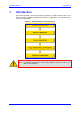
Installation Manual 1 1. Introduction Introduction This manual provides you with step-by-step procedures for initial and basic setup of the device, including hardware installation and software configuration. The flowchart below summarizes these steps: Figure 1-1: Required Steps to Install the Device Note: For detailed information on how to fully configure the device, refer to the device's User’s Manual. Version 6.
MediaPack Series Reader’s Notes Installation Manual 10 Document #: LTRT-59813
Installation Manual 2 2. Installing the Device Installing the Device This section describes the MP-11x (refer to 'Installing the MP-11x Series' on page 11) and MP-124 (refer to 'Installing MP-124' on page 20) hardware installation. This includes physical description, unpacking the shipped package, and mounting and cabling procedures. 2.1 Installing MP-11x This subsection describes the MP-11x hardware installation. 2.1.
MediaPack Series 2.1.1.2 MP-11x Rear Panel The device's rear panel provides the ports for cabling the device to the various interfaces. The figure below displays the rear panel of the MP-118 device (as an example). Figure 2-2: MP-11x (e.g., MP-118) Rear Panel The following table describes the MP-11x rear panel ports: Table 2-1: MP-11x Rear Panel Component Descriptions Item # Label 1 100-240~0.3A max. 2 Ethernet 3 RS-232 Component Description AC power supply socket. 10/100Base-TX Uplink port.
Installation Manual 4. 2.1.3 2. Installing the Device Ensure that in addition to the MP-11x unit, the package contains the following items: • AC power cable. • Small plastic bag containing four anti-slide bumpers for desktop installation. • Regulatory Information document. 5. Check, retain, and process any documents. 6. Notify AudioCodes or your local supplier of any damage or discrepancies.
MediaPack Series 2.1.3.1 Desktop Mounting Attach the four (supplied) anti-slide bumpers to the base of MP-11x and place it on a desktop in the desired position. 2.1.3.2 Wall Mounting Follow the procedure below for mounting MP-11x on a wall. ¾ To mount MP-11x on a wall: 1. 2.1.3.3 Drill four holes according to the following dimensions: • Horizontal distance between holes: 140 mm (5.51 inches) • Vertical distance between: 101.4 mm (4 inches) 2.
Installation Manual 3. 2. Installing the Device Attach the shelf to the rack using four standard rack screws (not supplied). Figure 2-5: MP-11x Rack Mount Table 2-3: MP-11x Rack Mount Item # Functionality 1 Standard rack holes used to attach the shelf to the rack. 2 Eight shelf-to-device screws. 2.1.4 Cabling MP-11x This section describes the MP-11x cabling procedures: ¾ To cable MP-11x: Connecting to the Ethernet network (refer to 'Connecting MP-11x to the Network' on page 16).
MediaPack Series 2.1.4.1 Connecting MP-11x to the Network Follow the procedure below for connecting MP-11x directly to the Ethernet network. ¾ To connect MP-11x directly to the Ethernet network: Using a crossover Ethernet cable with RJ-45 connectors on either end, connect the MP-11x Ethernet port (labeled Ethernet), directly to the network.
Installation Manual 2. Installing the Device ¾ To connect MP-11x to FXO or FXS devices: Using an RJ-11 two-wire telephone cords (refer to figure below for connector pinouts), connect MP-11x to the required telephone interfaces: • FXS: connect the MP-11x FXS ports (grouped under the label FXS) to fax machines, modems, or telephones. • FXO: connect the MP-11x FXO ports (grouped under the label FXO) to telephone exchange analog lines or PBX extensions. Figure 2-7: RJ-11 Phone Connector Pinouts 2.1.4.
MediaPack Series ¾ To cable the MP-11x FXS Lifeline: 1. Connect the Lifeline splitter to Port #1 on MP-11x (the Lifeline splitter is a special order option). 2. Connect the Lifeline phone to Port A on the Lifeline splitter. 3. Connect an analog PSTN line to Port B on the Lifeline splitter. Figure 2-9: Lifeline Cabling (Using Splitter Cable) for FXS-Only Devices ¾ To cable the combined MP-11x FXS/FXO Lifeline: 1. Connect a fax machine, modem, or phone to each of the FXS ports. 2.
Installation Manual 2.1.4.4 2. Installing the Device Connecting MP-11x RS-232 Port to a PC Follow the procedure below to connect the MP-11x serial (RS-232) interface to a PC using a straight-through, PS/2 to DB-9 cable adaptor. Notes: • This procedure is not applicable to MP-112 as this model does not provide an RS-232 serial interface port. • The PS/2 to DB-9 cable adaptor is not included in the MP-11x package. ¾ To connect MP-11x to a PC: 1.
MediaPack Series 2.1.4.5 Connecting MP-11x to Power MP-11x is powered from a standard AC electrical outlet. Warnings: • The device must be connected only by professional service personnel. • Ensure that the device connects to an electrical socket outlet that provides protective earthing (grounding). Prior to connecting power, refer to the Regulatory Information document supplied with the device. • Use only the AC power cord supplied with the device.
Installation Manual 2.2 2. Installing the Device Installing MP-124 This subsection describes the MP-124 hardware installation. 2.2.1 Physical Description The subsections below provide a physical description of the MP-124 front and rear panels. 2.2.1.1 MP-124 Front Panel The MP-124 front panel (shown in the figure below) provides LEDs for indicating various operating statuses. In addition, the front panel provides a reset button, described in the table below.
MediaPack Series 2.2.1.2 MP-124 Rear Panel The device's rear panel (shown in the figure below) provides the ports for cabling the device to the various interfaces. Figure 2-14: MP-124 Rear Panel - AC Power Model Figure 2-15: MP-124 Rear Panel - DC Power Model The table below describes the MP-124 rear panel components. Table 2-5: MP-124 Rear-Panel Component Descriptions Item # Label Component Description Protective earthing screw (mandatory for all installations). Accepts a 6-32 UNC screw.
Installation Manual 2.2.2 2. Installing the Device Unpacking and Checking Package Contents Follow the procedure below for unpacking the carton in which MP-124 is shipped. ¾ To unpack MP-124: 2.2.3 1. Open the carton and remove packing materials. 2. Remove the MP-124 unit from the carton. 3. Check that there is no equipment damage. 4.
MediaPack Series 2.2.3.2 19-inch Rack Mounting MP-124 can be installed in a standard 19-inch rack, by using two short, equal-length brackets (supplied).
Installation Manual 2. Installing the Device ¾ To install MP-124 in a 19-inch rack: 2.2.4 1. Remove the two screws located on one side of MP-124 (nearest the front panel). 2. Insert the peg on one of the brackets into the third air vent down on the column of air vents nearest the front panel. 3. Swivel the bracket until the holes in the bracket align with the two empty screw holes on MP-124. 4. Use the supplied screws to attach the bracket to the side of MP-124. 5.
MediaPack Series 2.2.4.1 Power Surge Protection and Grounding MP-124 This section discusses power surge protection and grounding of MP-124. Warning: • Ensure that you connect MP-124 to an electrical socket outlet that provides protective earthing (grounding). Prior to connecting power, refer to the Regulatory Information provided in the User’s Manual. For Finland: "Laite on liltettava suojamaadoituskoskettimilla varustettuun pistorasiaan." For Norway: "Apparatet rna tilkoples jordet stikkontakt.
Installation Manual 2. Installing the Device MP-124 must be installed in the Telecommunication rack. MP-124 grounding screw must be connected to the equipotential grounding bus bar located in the Telecommunication rack, using a wire of 6mm2 surface wire. This line must be connected to the equipotential bus bar of the electrical circuit board located in the Telecommunication room, using a stranded cable with surface area of 25 mm2.
MediaPack Series 2.2.4.2 Connecting MP-124 to the Ethernet Network Follow the procedure below for connecting MP-124 directly to the Ethernet network. ¾ To connect MP-124 directly to the Ethernet network: Using a crossover Ethernet cable with RJ-45 connectors on either end, connect the MP-124 Ethernet port (labeled ETHERNET), directly to the network.
Installation Manual 2.2.4.3 2. Installing the Device Connecting MP-124 to FXS Interfaces The MP-124 interfaces with the analog telephone interfaces by connecting to a main distribution frame (MDF), using a 50-pin Telco cable. MP-124 Safety Notice To protect against electrical shock and fire, use a 26 AWG min wire to connect analog FXS lines to the 50-pin Telco connector. Warning: To reduce noise interference, use a twisted pair Octopus cable that is terminated on a metal-hooded 50-pin Telco connector.
MediaPack Series 3. Connect the wire-pairs at the other end of the cable to a male 50-pin Telco connector (not supplied). 4. Insert and fasten the male connector to the female 50-pin Telco connector on the MP-124 rear panel (labeled Analog FXS Lines 1-24). 5.
Installation Manual 2.2.4.4 2. Installing the Device Connecting MP-124 RS-232 Port to a PC Follow the procedure below to connect the MP-124 serial (RS-232) interface to a PC using a standard, straight-through cable with DB-9 connectors on either end. ¾ To connect MP-124 to a PC: 1. Connect the DB-9 connector (refer to the figure below for connector pinouts) on one end of the cable to the MP-124 RS-232 port (labeled RS-232). 2.
MediaPack Series 2.2.4.5 Connecting MP-124 to Power MP-124 can be powered either from a standard AC electrical outlet or a 48-VDC power supply. The power configuration depends on the ordered MP-124 model. 2.2.4.5.1 AC Power Supply This section describes cabling of the MP-124 model for AC power. Warnings: • The device must be connected only by professional service personnel. • Ensure that the device connects to an electrical socket outlet that provides protective earthing (grounding).
Installation Manual 2. Installing the Device 2.2.4.5.2 DC Power Supply This section describes cabling of the MP-124 model for 48-VDC power supply. MP-124 DC Safety Notice When connecting MP-124 to a DC power supply, ensure that you adhere to the following safety guidelines: • Connect the device to a safety extra-low voltage (SELV) source that is sufficiently isolated from the mains.
MediaPack Series Reader’s Notes Installation Manual 34 Document #: LTRT-59813
Installation Manual 3 3. Configuring the Device Configuring the Device This section describes initial, basic setup configuration for the device, using the device's embedded Web server (Web interface). Notes: 3.1 • The device is supplied with application software (cmp file) already residing on its flash memory. This software is set to factory defaults. • If necessary, you can restore the device to factory defaults (refer to 'Restoring Factory Default Settings' on page 48).
MediaPack Series 3.1.1 Assigning an IP Address Using HTTP You can assign an IP address to the device, using the device's Web interface. ¾ To assign an IP address using HTTP: 1. Disconnect the device from the network and reconnect it to a PC using one of the following methods: • Using a hub or switch between a PC and the device: Connect the network interface on your PC to a port on a network hub / switch, using a standard Ethernet cable.
Installation Manual 4. 3.1.2 3. Configuring the Device Change the device's IP address, by performing the following: a. Open the ‘Multiple Interface Table’ page (Configuration tab > VoIP menu > Network submenu > IP Settings). b. Define the device's IP address, subnet mask, and default Gateway IP address (for “OAMP + Media + Control” application type) so that they correspond to your network IP scheme. c. Click Apply. d.
MediaPack Series 8. In the ‘Gateway’ field, enter the IP address of the default gateway (if any). 9. Click Apply to save the new client. 10. Click OK; the ‘Client Configuration’ screen closes. 11. Physically reset the device using the hardware reset button (or power down and then power up the device). This causes the device to use BootP; the device changes its network parameters to the values provided by BootP. Figure 3-2: BootP Client Configuration Screen 3.1.
Installation Manual 5. 6. 3. Configuring the Device c. Dial the new IP address. Use the star (*) key instead of periods (.), e.g., 192*168*0*4, and then press # to finish. d. Review the new IP address, and then press 1 to save. To change the subnet mask: a. Press 2 followed by the # key; The current subnet mask of the device is played. b. Press the # key. c. Dial the new subnet mask (e.g., 255*255*0*0), and then press # to finish. d. Review the new subnet mask, and then press 1 to save.
MediaPack Series # Configuration File Name Pattern Description 4 http://aa.bb.cc.dd:8080/config.ini HTTP on port 8080. 5 http://aa.bb.cc.dd:1400/config.ini HTTP on port 1400. 6 http://aa.bb.cc.dd/cgibin/acconfig.cgi?mac=&ip= Generating configuration per IP/MAC address dynamically, using a CGI script. See perl example below. c. 8. Press the selected pattern code, and then press # to finish. Press 1 to save, and then hang up the handset.
Installation Manual 3.1.4 3. Configuring the Device Assigning an IP Address Using CLI You can assign an IP address to the device, using command-line interface (CLI). Note: The CLI method for assigning an IP address is not applicable to MP-112 as this model does not provide RS-232 serial interface. ¾ To assign an IP address using CLI: 1. 2.
MediaPack Series 3.2 Configuring Basic SIP Parameters Once you have completed the previous sections, you are ready to start configuring the device using the Web interface. For information on how to fully configure the device, refer to the device's User’s Manuals. Tip: Once the device is configured, backup your settings by saving the configuration (ini) file to your PC.
Installation Manual 3.2.1 3. Configuring the Device Enabling Channels and Configuring Call Routing (Example) This section provides an example for enabling the device's channels and for configuring Tel (PSTN)-to-IP call routing. This includes assigning the channels a telephone number and then routing calls (e.g., of dialed numbers with prefix 10) from these channels to a specific IP destination (e.g., IP address 10.33.24.14). ¾ To enable channels and configure call routing: 1.
MediaPack Series The figure below shows an example of a configuration setup of two communicating FXS devices. Phones ‘101’ and '102' are connected to the first two channels of device with IP address 10.33.24.18; phone ‘120’ is connected to the first channel of device 10.33.24.14. The configuration in the 'Endpoint Phone Number Table' and ‘Tel to IP Routing Table’ pages (refer to the figure below) enables calls to be made between these two devices as well as between phones connected to the same device.
Installation Manual 3.3 3. Configuring the Device Saving Configuration and Resetting the Device To apply configuration changes to the device's volatile memory (RAM), click the Submit button located on the page in which you are configuring. Modifications to parameters with on-the-fly capabilities are immediately applied to the device; other parameters are applied only after a device reset.
MediaPack Series 3.4 Changing Login User Name and Password To prevent unauthorized access to the Web interface, two Web user accounts (login accounts) are available (primary and secondary) with assigned user name and password. For detailed information on the Web user accounts, refer to the device's User’s Manual.
Installation Manual 3.5 3. Configuring the Device Backing Up and Restoring Configuration You can save a copy/backup of the device's current configuration settings as an ini file to a folder on your PC. The saved ini file includes only parameters that were modified and parameters with other than default values. If the device has "lost" its configuration, you can restore the device's configuration by loading the previously saved ini file or by loading a newly created ini file.
MediaPack Series 3.6 Restoring Factory Defaults You can use the device's hardware Reset button to restore all the device's configuration settings to factory defaults, including the device's IP address and Web interface's login user name and password. Notes: • The device resets to the software version (cmp file) saved on its flash memory. • For additional methods to restore default settings, refer to the User's Manual. ¾ To restore MP-124 to factory default settings: 1.
Installation Manual 3.7 3. Configuring the Device Upgrading the Device You can upgrade the device with the following files: Firmware (cmp) file using the Web interface's Software Update Wizard (refer to ‘Upgrading Firmware’ on page 49). Auxiliary and ini files using the Web interface's 'Load Auxiliary Files' page (refer to 'Upgrading the ini and Auxiliary Files' on page 53). Note: When upgrading the firmware (cmp), you can also use the Software Update Wizard to load the ini and auxiliary files.
MediaPack Series ¾ To use the Software Upgrade Wizard: 1. Stop all traffic on the device (refer to the note above). 2. Open the 'Software Upgrade Wizard' (Maintenance tab > Software Update menu > Software Upgrade Wizard); the 'Software Upgrade Wizard' page appears. Figure 3-9: Start Software Upgrade Wizard Page 3. Click the Start Software Upgrade button; the 'Load a CMP file' Wizard page appears.
Installation Manual 3. Configuring the Device Note: At this stage, you can quit the Software Update Wizard, by clicking Cancel , without requiring a device reset. However, once you start uploading a cmp file, the process must be completed with a device reset. 4. Click the Browse button, navigate to the cmp file, and then click Send File; the cmp file is loaded to the device and you're notified as to a successful loading. 5.
MediaPack Series 9. In the 'FINISH' page, complete the upgrade process by clicking Reset; the device 'burns' the newly loaded files to flash memory and then resets the device. After the device reset, the 'End Process' screen appears displaying the burned configuration files (refer to the figure below). Figure 3-11: End Process Wizard Page 10.
Installation Manual 3.7.2 3. Configuring the Device Loading ini and Auxiliary Files You can load the device with a configuration file (i.e., ini file) and Auxiliary files (e.g., Call Progress Tones or Dial Plan files) for enhanced provisioning. For a detailed description of the Auxiliary files, refer to the device's User's Manual. Notes: • The current settings of parameters that are not included in the loaded ini file are retained (incremental). • After loading the ini file, the device does not reset.
MediaPack Series 3. Click the Load File button corresponding to the field that contains the file you want to load. 4. Save to flash memory and reset (if required) the device (refer to 'Saving and Resetting the Device' on page 44).
Installation Manual 4 4. Monitoring the Device Monitoring the Device You can monitor the operating status of the device by viewing one of the following: 4.1 Front-panel LEDs (refer to 'Front-Panel LEDs' on page 55). Home page of the Web interface (refer to 'Web Interface' on page 56).
MediaPack Series Label Type Color State Data Packet Status Green Blinking Transmitting RTP packets. Red Blinking Receiving RTP packets. - - Green On Off-hook or ringing. Red On Line malfunction. - - Telephone Interface Channels 4.2 Function No traffic. Normal. Web Interface The Web interface’s Home page allows online monitoring of the device.
Installation Manual 4.2.2 4. Monitoring the Device Viewing Channel Status The 'Home' page displays channel port icons that indicate the voice channels' operating status. You can use these port icons to drill down to view detailed channel status. For a detailed description of the 'Home' page, refer to the device's User's Manual.
Installation Manual Ver. 6.2 www.audiocodes.