
Installation guide


Fast Track Installation Guide 2. Installing the MP-11x
Version 4.6 11 July 2005
2.5 Cabling the MP-11x
Refer to Table 2-4 below for the cabling procedure for the MP-11x.
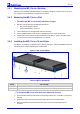
Figure
2-4: MP-118 Rear Panel Connectors
Table
2-3: MP-11x Rear Panel Component Descriptions
Item # Label Component Description
1 100-240~0.3A max. AC power supply socket
2 Ethernet 10/100 Base-TX Uplink port
3 RS-232 RS-232 status port (requires a DB-9 to PS/2 adaptor)
4 FXS 4 RJ-11 FXS ports (total 8)
5 Reset Reset button
2.5.1 Cables and Cabling Procedure
Verify that you have the cables listed under column ‘Cable’ in Table 2-4 before beginning to cable
the MP-11x according to the column ‘Cabling Procedure’.
Table
2-4: Cables and Cabling Procedure
Cable
Cabling Procedure
RJ-45 Ethernet
cable
Connect the Ethernet connection on the MP-11x directly to the network using a
standard RJ-45 Ethernet cable. For connector’s pinout refer to Figure 2-5 on page
12.
Note that when assigning an IP address to the MP-11x using HTTP (under step 1 in
Section 3.1.1), you may be required to disconnect this cable and re-cable it
differently.
RJ-11 two-wire
telephone cords
Connect the RJ-11 connectors on the rear
panel of the MP-11x to fax machine, modem,
or phones (refer to Figure 2-6).
Ensure that the FXS ports are
connected to the correct devices,
otherwise damage can occur.
RS-232 serial
cable
Insert the RS-232 straight serial cable into the RS-232 port using the DB-9 to PS/2
adaptor (not supplied). Connect the standard DB9 RS-232 connector on the other
end to a Terminal port. The pinout of the PS/2 connector is shown in Figure 2-7.
The RS-232 port is mainly used internally by service personnel for monitoring
purposes. Advanced users can also use this feature to obtain log information (for
example).
AC Power cable
Connect the MP-11x power socket to the mains.
1
2
3 4
4
5