
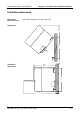
Technical data

Chapter 2 Assembly and installation guidelines Manual VIPA System 300S SPEED7
2-6 HB140E - CP - RE_343-1EX71 - Rev. 09/46
1 2 3
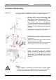
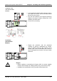
• Dismantle the according protection flaps of the
SPEED-Bus plug-in locations with a screw driver
(open and pull down).
For the SPEED-Bus is a parallel bus, not all
SPEED-Bus plug-in locations must be used in
series. Leave the protection flap installed at an
unused SPEED-Bus plug-in location.
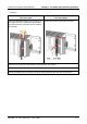
• At deployment of a DC 24V power supply, install it
at the shown position at the profile rail at the left
side of the SPEED-Bus and push it to the left to
the isolation bolt of the profile rail.
• Fix the power supply by screwing.
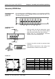
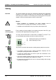
SLOT1
DCDC
CPU
SLOT2
• To connect the SPEED-Bus modules, plug it
between the triangular positioning helps to a
plug-in location marked with "SLOT ..." and pull it
down.
• Only the "SLOT1 DCDC" allows you to plug-in
either a SPEED-Bus module or an additional
power supply.
• Fix the modules by screwing.
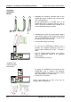
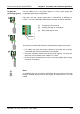
SLOT1
DCDC
CPU
SLOT2
• To deploy the SPEED7-CPU exclusively at the
SPEED-Bus, plug it between the triangular
positioning helps to the plug-in location marked
with "CPU SPEED7" and pull it down.
• Fix the CPU by screwing.
Please regard that not all CPU 31xS may be
deployed at the SPEED-Bus!
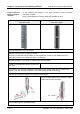
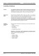
Installation
SPEED-Bus-
Module
Installation CPU
without Standard-
Bus-Modules