VIPA System 300S SPEED7 - CP | 343-1EX71 | Manual HB140E_CP | RE_343-1EX71 | Rev.
Copyright © VIPA GmbH. All Rights Reserved. This document contains proprietary information of VIPA and is not to be disclosed or used except in accordance with applicable agreements. This material is protected by the copyright laws.
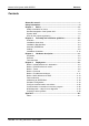
Manual VIPA System 300S SPEED7 Contents Contents About this manual .................................................................................... 1 Safety information .................................................................................... 2 Chapter 1 Basics .............................................................................. 1-1 Safety Information for Users................................................................. 1-2 General description of the System 300..............
Contents ii Manual VIPA System 300S SPEED7 HB140E - CP - RE_343-1EX71 - Rev.
Manual VIPA System 300S SPEED7 About this manual About this manual This manual describes the CP 343S-NET of the System 300S from VIPA. Here you may find besides of a product overview a detailed description of the modules. Overview Chapter 1: Basics This Basics contain hints for the usage and information about the project engineering of a SPEED7 system from VIPA. General information about the System 300S like dimensions and environment conditions will also be found.
Manual VIPA System 300S SPEED7 About this manual Objective and contents The manual describes the CP 343S-NET from VIPA. It contains a description of the construction, project implementation and usage. This manual is part of the documentation package with order number HB140E_CP and relevant for: Product Order number as of state: CP HW CP FW CP 343S-NET VIPA 343-1EX71 01 V217 Target audience The manual is targeted at users who have a background in automation technology.
Manual VIPA System 300S SPEED7 Safety information Safety information Applications conforming with specifications The CP is constructed and produced for: • for the deployment with VIPA SPEED-Bus • communication and process control • general control and automation applications • industrial applications • operation within the environmental conditions specified in the technical data • installation into a cubicle Danger! This device is not certified for applications in • in explosive environments (EX-zone)
Safety information 4 Manual VIPA System 300S SPEED7 HB140E - CP - RE_343-1EX71 - Rev.
Manual VIPA System 300S SPEED7 Chapter 1 Basics Chapter 1 Basics Overview This Basics contain hints for the usage and information about the project engineering of a SPEED7 system from VIPA. General information about the System 300S like dimensions and environment conditions will also be found. Content Topic Page Basics .............................................................................. 1-1 Chapter 1 Safety Information for Users...............................................................
Manual VIPA System 300S SPEED7 Chapter 1 Basics Safety Information for Users Handling of electrostatic sensitive modules VIPA modules make use of highly integrated components in MOSTechnology. These components are extremely sensitive to over-voltages that can occur during electrostatic discharges. The following symbol is attached to modules that can be destroyed by electrostatic discharges.
Manual VIPA System 300S SPEED7 Chapter 1 Basics General description of the System 300 The System 300 The System 300 is a modular automation system for middle and high performance needs, which you can use either centralized or decentralized. The single modules are directly clipped to the profile rail and are connected together with the help of bus clips at the backside. The CPUs of the System 300 are instruction set compatible to S7-300 from Siemens.
Manual VIPA System 300S SPEED7 Chapter 1 Basics System 300S Overview The CPUs 31xS are based upon the SPEED7 technology. This supports the CPU at programming and communication by means of co-processors that causes a power improvement for highest needs. Except of the basic variant, all SPEED7-CPUs are provided with a parallel SPEED-Bus that enables the additional connection of up to 10 modules from the SPEED-Bus periphery.
Manual VIPA System 300S SPEED7 Chapter 1 Basics SPEED-Bus The SPEED-Bus is a 32Bit parallel bus developed from VIPA with a maximum data rate of 40MByte/s. Via the SPEED-Bus you may connect up to 10 SPEED-Bus modules to your CPU 31xS. In opposite to the "standard" backplane bus where the modules are plugged-in at the right side of the CPU by means of single bus connectors, the modules at the SPEED-Bus are plugged-in at the left side of the CPU via a special SPEED-Bus rail.
Chapter 1 Basics Manual VIPA System 300S SPEED7 Operation Security • Wiring by means of spring pressure connections (CageClamps) at the front connector • Core cross-section 0.08...2.5mm2 • Total isolation of the wiring at module change • Potential separation of all modules to the backplane bus • ESD/Burst acc. IEC 61000-4-2/IEC 61000-4-4 (up to level 3) • Shock resistance acc.
Manual VIPA System 300S SPEED7 Chapter 1 Basics Hints for the project engineering Overview For the project engineering of a SPEED7 system please follow this approach: • Project engineering of the SPEED7-CPU and the internal DP master (if existing) as CPU 318-2DP (318-2AJ00-0AB00) • Project engineering of the real plugged modules at the standard bus • Project engineering of the internal Ethernet PG/OP channel after the real plugged modules as virtual CP 343-1 (Setting of IP address, subnet mask and gatewa
Manual VIPA System 300S SPEED7 Chapter 1 Basics The project engineering of the SPEED7-CPU has the following components: To be compatible with the Siemens SIMATIC manager, the following steps are required: Approach Standard bus Module Slot 1 CPU 318-2 2 DP X2 MPI/DP X1 3 real modules at the standard bus 343-1EX11 (internal PG/OP) 343-1EX11 (internal CP343) CPs res. DP master at the SPEED-Bus as 343-1EX11 res. 342-5DA02 342-5DA02 V5.
Manual VIPA System 300S SPEED7 Chapter 1 Basics The following illustration summarizes all project engineering steps: Summary SPEED-Bus (parallel) Standard bus (serial) Ethernet PG/OP internal DIO DP-Master Slot: 108 107 CP343 106 CP343 AO AI 105 104 103 DP-Master DO 102 101 DI CPU 31xS DO DIO AI AO 100 Ethernet PG/OP internal internal CP 343 if available Slot: 108 107 106 105 104 103 102 101 100 Se ttin go f th es lot loc at ion via DP master system for SPEED-Bu
Chapter 1 Basics Manual VIPA System 300S SPEED7 Hint, valid for all SPEED-Bus modules! The SPEED-Bus always requires the Siemens DP master CP 342-5 (342-5DA02 V5.0) as last module to be included, connected and parameterized to the operation mode DP master. Every SPEED-Bus module has to be connected as VIPA_SPEEDbus slave into this master system.
Manual VIPA System 300S SPEED7 Chapter 2 Assembly and installation guidelines Chapter 2 Assembly and installation guidelines Overview In this chapter you will find all information, required for the installation and the cabling of a process control with the components of the System 300. Content Topic Page Assembly and installation guidelines............................ 2-1 Chapter 2 Overview ..............................................................................................
Chapter 2 Assembly and installation guidelines Manual VIPA System 300S SPEED7 Overview While the standard peripheral modules are plugged-in at the right side of the CPU, the SPEED-Bus peripheral modules are connected via a SPEEDBus bus connector at the left side of the CPU. VIPA delivers profile rails with integrated SPEED-Bus for 2, 6 or 10 SPEED-Bus peripheral modules with different lengths.
Manual VIPA System 300S SPEED7 Chapter 2 Assembly and installation guidelines Installation dimensions Dimensions Basic enclosure 1tier width (WxHxD) in mm: 40 x 125 x 120 40mm 122mm 65mm Dimensions Installation dimensions 125mm 125 mm 120mm 175mm HB140E - CP - RE_343-1EX71 - Rev.
Chapter 2 Assembly and installation guidelines Manual VIPA System 300S SPEED7 Installation Standard-Bus Approach If you do not deploy SPEED-Bus modules, the assembly at the standard bus happens at the right side of the CPU with the following approach: • Bolt the profile rail with the background (screw size: M6), so that you still have minimum 65mm space above and 40mm below the profile rail.
Manual VIPA System 300S SPEED7 Chapter 2 Assembly and installation guidelines Assembly SPEED-Bus Pre-manufactured SPEED-Bus profile rail For the deployment of SPEED-Bus modules, a pre-manufactured SPEEDBus rail is required. This is available mounted on a profile rail with 2, 6 or 10 extension plug-in locations.
Chapter 2 Assembly and installation guidelines Manual VIPA System 300S SPEED7 Installation SPEED-BusModule 1 2 3 • Dismantle the according protection flaps of the SPEED-Bus plug-in locations with a screw driver (open and pull down). For the SPEED-Bus is a parallel bus, not all SPEED-Bus plug-in locations must be used in series. Leave the protection flap installed at an unused SPEED-Bus plug-in location.
Manual VIPA System 300S SPEED7 Chapter 2 Assembly and installation guidelines Installation CPU with Standard-BusModules • If also standard modules shall be plugged, take a bus coupler and click it at the CPU from behind like shown in the picture. • Plug the CPU between the triangular positioning helps to the plug-in location marked with "CPU SPEED7" and pull it down. • Fix the CPU by screwing.
Chapter 2 Assembly and installation guidelines Manual VIPA System 300S SPEED7 Cabling Overview The power supplies and CPUs are exclusively delivered with CageClamp contacts. For the signal modules the front connectors are available from VIPA with screw contacts. In the following all connecting types of the power supplies, CPUs and input/output modules are described.
Manual VIPA System 300S SPEED7 CageClamp technology (green) 1 Chapter 2 Assembly and installation guidelines For the cabling of e.g. the power supply of a CPU, green plugs with CageClamp technology are deployed. Here also you may connect wires with a cross-section of 0.08mm2 to 2 2.5mm . You can use flexible wires without end case as well as stiff wires.
Manual VIPA System 300S SPEED7 Chapter 2 Assembly and installation guidelines Front connectors of the in-/output modules In the following the cabling of the three variants of the front-facing connector is shown: For the I/O modules the following plugs are available at VIPA: 20pole screw connection VIPA 392-1AJ00 40pole screw connection VIPA 392-1AM00 Open the front flap of your I/O module. Bring the front connector in cabling position.
Manual VIPA System 300S SPEED7 Chapter 2 Assembly and installation guidelines ... continue 20pole screw connection VIPA 392-1AJ00 Push the release key at the front connector on the upper side of the module and at the same time push the front connector into the module until it locks. 40pole screw connection VIPA 392-1AM00 Bolt the fixing screw of the front connector. Now the front connector is electrically connected with your module. Close the front flap.
Chapter 2 Assembly and installation guidelines Manual VIPA System 300S SPEED7 Installation Guidelines General The installation guidelines contain information about the interference free deployment of System 300 systems. There is the description of the ways, interference may occur in your control, how you can make sure the electromagnetic digestibility (EMC), and how you manage the isolation.
Manual VIPA System 300S SPEED7 Basic rules for EMC Chapter 2 Assembly and installation guidelines In the most times it is enough to take care of some elementary rules to guarantee the EMC. Please regard the following basic rules when installing your PLC. • Take care of a correct area-wide grounding of the inactive metal parts when installing your components. - Install a central connection between the ground and the protected earth conductor system.
Chapter 2 Assembly and installation guidelines Isolation of conductors Manual VIPA System 300S SPEED7 Electrical, magnetic and electromagnetic interference fields are weakened by means of an isolation, one talks of absorption. Via the isolation rail, that is connected conductive with the rack, interference currents are shunt via cable isolation to the ground.
Manual VIPA System 300S SPEED7 Chapter 3 Hardware description Chapter 3 Hardware description Overview Here the hardware components of the CP 343S-NET are more described. The technical data are to be found at the end of the chapter. Content Topic Page Hardware description ..................................................... 3-1 Chapter 3 Properties............................................................................................. 3-2 Structure ...............................................
Manual VIPA System 300S SPEED7 Chapter 3 Hardware description Properties General The CP 343S-NET in the following may only be used at the SPEED-Bus. CP 343S-NET PWR RUN STOP SF L/A S RUN STOP VIPA 343-1EX71 X 2 3 4 CP 343S-NET Order data 3-2 • • • • • • • Ethernet CP 343S-NET for SPEED-Bus, order no.
Manual VIPA System 300S SPEED7 Chapter 3 Hardware description Structure Front view [1] [2] CP 343S-NET PWR RUN STOP SF 1 L/A S RUN STOP The following components are under the front flap [3] 2 LED status indicators Operating mode switch Twisted pair interface for Ethernet X 2 VIPA 343-1EX71 3 4 X1 3 Components 1 2 3 4 5 6 7 8 RJ45 jack Via the RJ45 jack you may connect the CP 343S-NET - SPEED-Bus to Ethernet.
Manual VIPA System 300S SPEED7 Chapter 3 Hardware description LEDs The CP 343S-NET carries a number of LEDs that are available for diagnostic purposes on the bus and for displaying the local status. These give information according to the following pattern over the operating condition of the CP: PWR RUN STOP green green yellow SF red ○ ● ● ● ● ● ● ● ● on: ○ ● ● ○ ○ ○ ○ ● ○ ● ○ ○ X X X ○ ○ CP is not power supplied, or there may be a defect.
Manual VIPA System 300S SPEED7 Chapter 3 Hardware description Power supply The Ethernet CP 343S-NET - SPEED-Bus receives power via the backplane. Here the max. current consumption amounts to max. 550mA. Firmware update There is the possibility to execute a firmware update of the CP 343S-NET among others via the SPPED7 CPU by means of a MMC.
Manual VIPA System 300S SPEED7 Chapter 3 Hardware description Technical data Electrical data Power supply Current consumption Power dissipation Isolation Status indicator Connectors/interfaces Ethernet interface RJ45 Baud rate Overall length Configurable connections Maximum number of productive connections by Siemens NetPro Maximum Number of productive connections by user program Siemens S7 connections TCP connections ISO-on-TCP connections (RFC1006) UDP connections UDP Broadcast connection UDP Multicast
Manual VIPA System 300S SPEED7 Chapter 4 Deployment Chapter 4 Deployment Overview Content of this chapter is the functionality of the CP 343S-NET for SPEEDBus from VIPA. The module may only be used at a SPEED-Bus slot at the left side of the CPU. Content Topic Page Deployment ..................................................................... 4-1 Chapter 4 Basics - Industrial Ethernet in automation ............................................ 4-2 Basics - ISO/OSI reference model ...................
Manual VIPA System 300S SPEED7 Chapter 4 Deployment Basics - Industrial Ethernet in automation Overview The flow of information in a company presents a vast spectrum of requirements that must be met by the communication systems. Depending on the area of business the bus system or LAN must support a different number of users, different volumes of data must be transferred and the intervals between transfers may vary, etc.
Manual VIPA System 300S SPEED7 Chapter 4 Deployment Basics - ISO/OSI reference model Overview The ISO/OSI reference model is based on a proposal that was developed by the International Standards Organization (ISO). This represents the first step towards an international standard for the different protocols. It is referred to as the ISO-OSI layer model. OSI is the abbreviation for Open System Interconnection, the communication between open systems.
Chapter 4 Deployment Layers Manual VIPA System 300S SPEED7 Layer 1 Bit communication layer (physical layer) The bit communication layer (physical layer) is concerned with the transfer of data bits via the communication channel.
Manual VIPA System 300S SPEED7 Layers continued... Chapter 4 Deployment Layer 5 Session layer The session layer is also called the communication control layer. It relieves the communication between service deliverer and the requestor by establishing and holding the connection if the transport system has a short time fail out. At this layer, logical users may communicate via several connections at the same time. If the transport system fails, a new connection is established if needed.
Chapter 4 Deployment Manual VIPA System 300S SPEED7 Basics - Terms Network (LAN) A network res. LAN (local area network) provides a link between different stations that enables them to communicate with each other. Network stations consist of PCs, IPCs, TCP/IP adapters, etc. Network stations are separated by a minimum distance and connected by means of a network cable. The combination of network stations and the network cable represent a complete segment.
Manual VIPA System 300S SPEED7 Chapter 4 Deployment Basics - Protocols Overview Protocols define a set of instructions or standards that enable computer to establish communication connections and exchange information as error free as possible. A commonly established protocol for the standardization of the complete computer communication is the so-called ISO/OSI layer model, a model based upon seven layers with rules for the usage of hardware and software (see ISO/OSI reference model above).
Chapter 4 Deployment Manual VIPA System 300S SPEED7 TCP/IP TCP/IP protocols are available on all major systems. At the bottom end this applies to simple PCs, through to the typical mini-computer up to mainframes. For the wide spread of Internet accesses and connections, TCP/IP is often used to assemble heterogeneous system pools. TCP/IP, standing for Transmission Control Protocol and Internet Protocol, collects a various range of protocols and functions.
Manual VIPA System 300S SPEED7 Chapter 4 Deployment Properties TCP/IP • Besides of the IP address ports are used for the addressing. A port address should be within the range of 2000...65535. Partner and local ports may only be identical at one connection. • Not depending on the used protocol, the PLC needs the VIPA handling blocks AG_SEND (FC 5) and AG_RECV (FC 6) for data transfer. UDP The UDP (User Datagram Protocol) is a connection free transport protocol.
Chapter 4 Deployment Manual VIPA System 300S SPEED7 ISO transport (once H1) The ISO transport service (ISO 8073 class 4) corresponds to the transport layer (Layer 4) of the ISO/OSI reference model. With ISO transport connections there is the possibility for program and event controlled communication via Industrial Ethernet. Here data blocks may be exchanged bi-directional. The ISO transport connection offers services for a safety transfer of data by means of configured connections.
Manual VIPA System 300S SPEED7 Chapter 4 Deployment Basics - IP address and subnet IP address structure Industrial Ethernet exclusively supports IPv4. At IPv4 the IP address is a 32Bit address that must be unique within the network and consists of 4 numbers that are separated by a dot. Every IP address is a combination of a Net-ID and a Host-ID and its structure is as follows: xxx.xxx.xxx.xxx Range: 000.000.000.000 to 255.255.255.255 The network administrator also defines IP addresses.
Manual VIPA System 300S SPEED7 Chapter 4 Deployment Address classes For IPv4 addresses there are five address formats (class A to class E) that are all of a length of 4byte = 32bit.
Manual VIPA System 300S SPEED7 Chapter 4 Deployment Basics - MAC address and TSAP MAC address There is a unique MAC address (Media Access Control) necessary for each CP. Usually a module is labeled with its MAC address by the manufacturer. This address should be used for project engineering of the CP. The MAC address has a length of 6 bytes. On delivery the first three bytes specify the manufacturer. These bytes are assigned by the IEEE committee. The last three bytes may be assigned by the manufacturer.
Chapter 4 Deployment Manual VIPA System 300S SPEED7 Fast introduction Overview At the first start-up respectively at an over all reset the Ethernet CP 343SNET - SPEED-Bus does not have any IP address. The CP may only be contacted by its MAC address. IP address parameters may be assigned to the CP by means of the MAC address, which may be found on a label beneath its front flap. The assignment takes place directly via the hardware configuration of the Siemens SIMATIC manager.
Manual VIPA System 300S SPEED7 Chapter 4 Deployment Assign IP parameters You get valid IP address parameters from your system administrator. For the assignment of the IP address parameters such as IP address, Subnet mask etc. you have the following possibilities: • Online using Siemens SIMATIC manager via "Assign Ethernet Address" (at least CP-Firmware 1.7.4) • With a project with IP address and IP parameters transferred via MMC or MPI to the CPU.
Manual VIPA System 300S SPEED7 Chapter 4 Deployment ... continue • Configure the internal PG/OP channel directly under the really plugged modules as virtual CP 343-1 (343-1EX11) from Siemens and set IP address, subnet mask and gateway at CP properties. • If used always configure as 2. CP the internal CP 343 of a CPU 31xSN/NET as CP 343-1 (343-1EX11) by setting another IP address, subnet mask and gateway. Else configure as 2.
Manual VIPA System 300S SPEED7 Chapter 4 Deployment Link-up stations For the project engineering of connections, connected stations are presumed. To link-up stations, point on the colored net mark of the according CP with the mouse and drag it to the network you want to assign. The connection is displayed graphically by a line. Configure connections For the project engineering of new connections click on the according CPU and choose "Insert new connection” from the context menu.
Manual VIPA System 300S SPEED7 Chapter 4 Deployment Addressing at SPEED-Bus Overview To provide specific addressing of the installed peripheral modules, certain addresses must be allocated in the CPU. With no hardware configuration present, the CPU assigns automatically peripheral I/O addresses during boot procedure depending on the plug-in location amongst others also for plugged modules at the SPEED-Bus.
Manual VIPA System 300S SPEED7 Chapter 4 Deployment Hardware configuration The project engineering of the Ethernet CP 343S-NET - SPEED-Bus takes place at the Siemens hardware configurator and is divided into 2 parts: • Project engineering and connecting at the standard bus as Siemens CP 343-1 (343-1EX11) • Project engineering as single VIPA_SPEEDBUS DP slave with CP 3431EX71 at a virtually DP master (SPEEDBUS.GSD necessary).
Chapter 4 Deployment Requirements Manual VIPA System 300S SPEED7 The hardware configurator is a part of the Siemens SIMATIC manager. It serves the project engineering. The modules that may be configured here are listed in the hardware catalog. For the deployment of the System 300S modules at the SPEED-Bus, the inclusion via the GSD-file SPEEDBUS.GSD from VIPA in the hardware catalog is required.
Manual VIPA System 300S SPEED7 Steps of project engineering Chapter 4 Deployment The following text describes the approach of the project engineering in the hardware configurator from Siemens at an abstract sample. The project engineering is separated into the following parts: • Project engineering of the CPU as CPU 318-2DP (318-2AJ00-0AB00 V3.0) • Project engineering of the real plugged modules at the standard bus • Project engineering of the Ethernet PG/OP channel.
Manual VIPA System 300S SPEED7 Chapter 4 Deployment Project engineering of the real modules at the standard bus The modules at the right side of the CPU at the standard bus are configured with the following approach: • Include your System 300 modules at the standard bus in the plugged sequence starting with slot 4. • Parameterize the CPU res. the modules where appropriate. The parameter window opens by a double click on the according module.
Manual VIPA System 300S SPEED7 Chapter 4 Deployment Due to the fact that a Ethernet CP 343S-NET - SPEED-Bus is in project engineering and parameterization similar to the CP 343-1 from Siemens, every Ethernet CP 343S-NET - SPEED-Bus is inserted at the standard bus as CP 343-1 (343-1EX11) after the already configured modules. The sequence follows the one at the SPEED-Bus from the right to the left.
Manual VIPA System 300S SPEED7 Chapter 4 Deployment The slot assignment of the SPEED-Bus modules and the parameterization of the in-/output periphery happens via a virtual Profibus DP master system. For this, place as last module a DP master (342-5DA02 V5.0) with master system. For the employment of the System 300S modules at the SPEED-Bus the inclusion of the System 300S modules into the hardware catalog via the GSD-file SPEEDBUS.GSD from VIPA is required. After the installation of the SPEEDBUS.
Manual VIPA System 300S SPEED7 Configure CPU via Ethernet with CP 343 - SPEED-Bus Chapter 4 Deployment The following approach requires that the Ethernet CP 343S-NET - SPEEDBus is available online, i.e. you assigned an IP address and subnet mask via a hardware configuration and the project engineering PC is in the same IP number circle. For more information see "Access to the Ethernet PG/OP channel and website..." above. • Adjust the following setting in the SIMATIC manager at Options > PG/PC interface...
Manual VIPA System 300S SPEED7 Chapter 4 Deployment Configure communication connections Overview The project engineering of connections i.e. the "link-up" between stations happens in NetPro from Siemens. NetPro is a graphical user interface for the link-up of stations. A communication connection enables the program controlled communication between two participants at the Industrial Ethernet.
Manual VIPA System 300S SPEED7 Chapter 4 Deployment Note! All stations outside of the recent project must be configured as replacement objects like e.g. Siemens "SIMATIC S5" or "other station" or with the object "In unknown project". When creating a connection you may also choose the partner type "unspecified" and set the required remote parameter directly in the connection dialog.
Manual VIPA System 300S SPEED7 Chapter 4 Deployment You receive the following graphical display for every PLC station and their component. By selecting the single components, the context menu offers you several functions: PLC stations 1 Station 1 CPU DP 318-2 1 2 MPI 3 1 CP CP 343-1 343-1 4 5 2 3 4 5 Link up stations Station This includes a PLC station with rack, CPU and communication components.
Manual VIPA System 300S SPEED7 Projecting connections Chapter 4 Deployment For the project engineering of connections, open the connection list by selecting the according CPU. Choose Insert new connection in the context menu: Station 1 CPU DP 318-2 MPI CP CP 343-1 343-1 insert new connection Connection partner (partner station) A dialog window opens where you may choose the connection partner and the connection type.
Chapter 4 Deployment Manual VIPA System 300S SPEED7 Connection types The following connection types are available for communication: • Siemens S7 connections, Send/Receive connections (TCP, ISO-onTCP and ISO transport) for secured data transfer of data blocks between two Ethernet stations • UDP for not secured data transfer of data blocks between two stations. Open the properties dialog Choose the connection partner and the type of connection and confirm with [OK].
Manual VIPA System 300S SPEED7 Siemens S7 connection Chapter 4 Deployment For data transfer with Siemens S7 connections the FB/SFB VIPA handling blocks are necessary; the deployment is described in the manual "Operation list" of your CPU. At Siemens S7 connections the communication connections are specified by a connection ID for each communication partner. A connection is specified by the local and partner connection end point. A link. At Siemens S7 connections the TSAPs must be congruent crosswise.
Chapter 4 Deployment Manual VIPA System 300S SPEED7 Block parameters Local ID The ID is the link to your PLC program. The ID must be identical to the ID of the call interface of the FB/SFB VIPA handling block. [Default] As soon as you click at [Default], the ID is reset to system generated ID. Connection path In this part of the dialog window the connection path between the local and the partner station may be set.
Manual VIPA System 300S SPEED7 Send/Receive connections Chapter 4 Deployment At the PLC side for data transfer with these connections the VIPA handling blocks AG_SEND (FC 5) and AG_RECV (FC 6) are to be used.
Chapter 4 Deployment Manual VIPA System 300S SPEED7 General information In this tab the general connection parameters are listed, which identify the local connection end point. ID This entry is identical to the entry of the connection table. The value may always be changed. Please also regard to adjust the ID parameter of the call interface of the FC. Note! If a CP is exchanged by another one, this must at least provide the same services and must at least have the same version level.
Manual VIPA System 300S SPEED7 Chapter 4 Deployment Options Dependent on the specification of the connecting partner the operating mode may be set respectively displayed. Mode SEND/RECEIVE The SEND/RECEIVE interface allows the program-controlled communication to any partner station via a configured connection. Here the data transfer happens by a call from your user application. The FC5 and FC6 that are part of the VIPA block library are serving as interface.
Chapter 4 Deployment Manual VIPA System 300S SPEED7 Communication connections in the user program Overview For the execution of connection commands at the PLC, your CPU requires an user application. For this, exclusively the VIPA handling blocks are to be used, which you may get as library from VIPA. More information about the deployment of the blocks may be found in the manual "Operation list" of the CPU.
Manual VIPA System 300S SPEED7 Function blocks FB/SFB FB/SFB 8 FB/SFB 9 FB/SFB 12 FB/SFB 13 FB/SFB 14 FB/SFB 15 FB 55 Chapter 4 Deployment The following function blocks may be used for Siemens S7 communications. More information about the deployment of the blocks may be found in the manual "Operation list" of the CPU. Label USEND Description Uncoordinated data transmission FB/SFB 8 USEND may be used to transmit data to a remote partner FB/SFB of the type URCV (FB/SFB 9).
Chapter 4 Deployment User program at Send/Receive connections Manual VIPA System 300S SPEED7 The following connections are Send/Receive connections: • TCP (SEND-RECEIVE, FETCH-WRITE PASSIVE) • ISO-on-TCP (SEND-RECEIVE, FETCH-WRITE PASSIVE) • ISO Transport (SEND-RECEIVE, FETCH-WRITE PASSIVE) • UDP (SEND-RECEIVE) For the communication between CPU and CP, the following FCs are available: AG_SEND (FC 5) This block transfers the user data from the data area given in SEND to the CP specified via ID and LADDR.
Manual VIPA System 300S SPEED7 Chapter 4 Deployment FC call is faster than CP transfer time If a block is called a second time in the user application before the data of the last time is already completely send res. received, the FC block interface reacts like this: AG_SEND No command is accepted until the data transfer has been acknowledged from the partner via the connection. Until this you receive the message "Order running" before the CP is able to receive a new command for this connection.
Manual VIPA System 300S SPEED7 Chapter 4 Deployment AG_SEND (FC 5) By means of AG_SEND the data to send are transferred to the CP. Parameter Parameter ACT Declaration Input Type BOOL ID LADDR Input Input INT WORD SEND LEN DONE Input Input Output ANY INT BOOL ERROR Output BOOL STATUS Output WORD AG_RECV (FC 6) By means of AG_RECV the data received from the CP are transferred to the CPU.
Manual VIPA System 300S SPEED7 DONE, ERROR, STATUS DONE (SEND) 1 0 0 0 0 0 Chapter 4 Deployment The following table shows all messages that can be returned by the CP after a SEND res. RECV command. A "-" means that this message is not available for the concerning SEND res. RECV command.
Manual VIPA System 300S SPEED7 Chapter 4 Deployment ... continue DONE NDR (SEND) (RECV) 0 - ERROR STATUS Description 1 8F42h - 0 1 8F43h 0 - 1 8F44h - 0 1 8F45h 0 0 1 8F7Fh 0 0 1 8090h 0 0 0 0 0 0 0 0 0 0 0 0 0 0 0 0 0 0 0 0 0 1 1 1 1 1 1 1 1 1 1 1 8091h 8092h 80A0h 80A4h 80B0h 80B1h 80B2h 80C0h 80C1h 80C2h 80C3h 0 0 1 80C4h 0 0 1 80D2h Status parameter at reboot 4-42 Acknowledgement delay at reading a parameter from peripheral area.
Manual VIPA System 300S SPEED7 Chapter 4 Deployment NCM diagnostic – Help for error diagnostic Check list for error search This page shall help you with the error diagnostic. The following page lists a number of typical problems and their probable causes: Question CPU in Run? AG_SEND, AG_RECV in user application? Is CP able to connect? Can data be transferred? Is the complete data block sent at ISO-onTCP? Siemens NCM S7 diagnostic Solution with "no" Control DC 24V voltage supply.
Manual VIPA System 300S SPEED7 Chapter 4 Deployment Start NCM diagnostic There are two options to start the diagnostic tool: • Via Windows-START menu > SIMATIC ... NCM S7 > Diagnostic • Within the project engineering res. the hardware configuration via the register "Diagnostic" in the "Property" dialog with [Execute]. Structure The working surface of the diagnostic tool has the following structure: The navigation area at the left side contains the hierarchical listed diagnostic objects.
Manual VIPA System 300S SPEED7 Chapter 4 Deployment Read diagnostic buffer The CP has a diagnostic buffer. This has the architecture of a ring memory and may store up to 100 diagnostic messages. The NCM diagnostic allows you to monitor and evaluate the CP diagnostic messages via the diagnostic object Diagnostic buffer. Via a double click on a diagnostic message the NCM diagnostic shows further information.
Manual VIPA System 300S SPEED7 Chapter 4 Deployment Coupling to other systems Overview The operating mode FETCH/WRITE supported at TCP res. ISO-on-TCP can be used for accesses of partner devices to the PLC system memory. To be able to use this access also for example for implementation in PC applications you have to know the telegram structure for orders. The specific headers for request and acknowledgement telegrams have per default a length of 16Byte and are described at the following pages.
Manual VIPA System 300S SPEED7 Chapter 4 Deployment Note! Information about the valid range can be found at the technical data of your CPU. ORG identifier 05h-07h CPU area ORG identifier Description PB 05h Source/destination data from/into peripheral modules. Input module for source data, output module for destination data. ZB 06h Source/destination data from/into counter cells. TB 07h Source/destination data from/into timer cells.
Manual VIPA System 300S SPEED7 Chapter 4 Deployment Structure of PLCHeader WRITE FETCH For every READ and WRITE the CP generates PLC header for request and acknowledgment messages.
Manual VIPA System 300S SPEED7 Index Appendix A Index A I Address at start-up ....................... 4-11 Addressing SPEED-Bus............................. 4-18 AG_RECV (FC 6) ......................... 4-40 AG_SEND (FC 5) ......................... 4-40 Application layer ............................. 4-5 Assembly ................................. 2-1, 2-4 CPU 31xS ................................. 2-4 Direction.................................... 2-2 SPEED-Bus ..............................
Manual VIPA System 300S SPEED7 Index Project engineering ...................... 4-14 Properties ....................................... 3-2 R RFC1006 ........................................ 4-9 Hint ......................................... 1-10 Structure.......................................... 3-3 Subnet mask................................. 4-11 Switch.............................................. 4-6 T S Safety Information .......................... 1-2 Security layer ...........................