
User Guide

Amplifier
Status Display
WindoW:
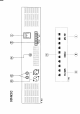
The
status display window highliehts the operating conditions of the DCM120.
Please refer to Figure #1
on
the back
page
ofthis instruction
sheet with numerical reference as follows:
t
High TempefatUfe: This red LED
glows
if
the hn has failed and
the amplifier
has
been shut down
by
its'
temperature
control
circuitry. If this
LED
is
glowing
and the
fans have not
ftiled,
it means
that the amplifio is operating in
an ambient
environme,nt
that it naturally
too hot for
ftn
cooling to make any
difference to the temperature of the amplifier.
Z
PoWef: This LED
glows green
if AC
power
is switched
on to the DCM120. Note
that this LED does not indicate
the
pres€nce
of a DC supply
voltage
tlains
Failure:
The LED
glows
red
if there is
a ftilure
in
the AC mains
power
supply. However,
this LED will
only
glow
if
there is a DC
supply voltage
present.
If no DC
supply voltage is
preseirt
then this LED
will not
glow.
Output Level
VU
ileter:
A 10
segment LED w meter is
provided
to
give
an indication of
the output signal level
of
the DCMI2O
from
-25
to
+3
dB. For
normal op€ration
the LED's
should oscillate
in
and out
of the
red
zone.
tf
the LED's
in
the red
zone
are lit continually,
then
the output level
control
(or
the level of
the
input
signal to the DCMI2O)
should
be
adjusted
to reduce
the
output
level.
Too much
output level
can cause distortion
and
possible
damage to the
cornected speaker
system.
Rear Panel
Gonnections
Please
refer
to Figure #2 on
the back
page
of these instructions with
numerical references
as
follorrys:
3 Pin
lEC,
AC Mains Power
lnlet.
The
operating voltage is 240
VAC
@
50Hzor 110 VAC
@
60llz. The
AC
power
voltage
level is
not externally
user selectable
but is factory
prs'set
(via
transformer
selection). The inlet is
equipped
with
an
inbuilt
AC
fuse holder fitted
with
a
4
Amp
slow blow fuse
plus
one spare fuse. Power
consumption
is
300 VA. Please
ensure that the mains
power
cord is
disconnected
before attempting
to check or rephce
this fuse.
Output
Terminal
Strip . Reading
from left to
right these connections
are as follows:
Common
for low impedance
4
Ohms
8 Ohms
Common
for constant
voltage systems
70 volts
100 volts
24 VDC
Power
Connection.
rhe
left
side
red
post
is the
+
(positive)
terminal while
the right side black
post
is the
-
(negative)
terminal. The DC
curr€nt
drain is
8 Amps, manimum
at full
power.
This
socket also
provides
trickle
charge to
a
DC
battery
supply
(if
connected)
when
the DCM120 is
operated from AC mains
power.
The level
of trickle
charge
is
300 md
maximum.
DC Low
Voltage
Fuse Receptacle.
Access
the DC fuse
by turning the
cap
half
a tum counter-clockwise
with
a
screwdriver. The value
of the fuse is l0
Amps Please
ensure that
the AC
power
switch
is in the
'ofr
position
and
that the
mains
power
cord
is
disconnected before
attenpting
to
check or replace this
fusc
lnput
(&
Parallel
Output)
XLR Signal
Connection.
The
input to the DCM120
is transformer
balanced
@
10K
ohms. The
pin
configuration of
both sockas is
as follows:
pin
#l-earth;
pin
#2-active
(hrgh,
+);
pin
#3-active
(low,
-).
The
output
socket is
to allow the
original input
signal to be fed
on to another
amplifier. As
these two
sockets are wired in
passive parallel,
the failure
of any
one amplifier
will not
affect the signal flowing
through
that
amplifia to another amplifier.