
User Guide
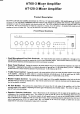

7. Limit
LED: This red LED is designed
to
give
the us€r an
indication
of the operating
condilion of the amptifier and is
integral
to the
inbuilt
protection
included in the
amplifier.
This LED will
glow
red if the amplifier is operating
into
an excessive
load
or
ifone
or mor€ of the input
channels
is
supplving an unacceptably high
level
ofsignal. It is
normal
for this
LED
to flicker
on and
off
howwer. if
it
glows
steaqt^ . the amplifier will
shul
down for a
period
of approximately 3 seconds and continue to
cycle
in
this fashion
until the abnormal connection is removed
or
rectified. This is
a
featue
of the amplifier designed to
protect
the
amplifier circuitry
ald the speaken
connected to the output.
Powef
Button:
ThiE
switch controls the swilching of AC
power
to the amplifier. Rocking this switch upwards
turns on
AC
power
to the amplifier
while rockhg
the switch downwards turns
power
off to the amplifier. When in the upard
positio4
the red neon in
the body of
the switch will
glow.
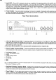
Rear Panel Connections
t. 3 Pin IEC ilains
Power Inlet:
the
operating voltage is 240 VAC
@
50Hz
or
lloVAC@60H2.
The AC
power
voltage level is not
extemally user adjustable
but is factory
pre-set.
The intet is
equippea with
an
inhilt AC
fus€ holder fitted
with a 4
amp ftse
(ATl20)
or a 2
amp fuse
(AT60)
plus
a spare
for
each found within the holder.
Fower conslmption is 225VA
for the ATl20
and l25VA for the 4T60.
* Please ensure
that the mains
prower
cord is dhconnected
before attempting to ch€ck
or
r€place
this fuse.
z. Direct Output
Terminal
Strip: fnese
screw terminals allow
access to the direct outpurs of rhe amplifier. 2
spare
screw terminals
allow for the connection
ofvarious tone module accessories. Reading from
left to right the terminals
are-
o
Low Impedance
Common
o
4
Ohms
(Not
aYailable
on
AT60)
.8Ohms
.
Constant Voltage
Common
.
T0
Volt Line
.
l@ Volt Line
o
Spare
o
Spare
Note:
The minimum impedance
at any time
on maximum load for 100 Volt line
shoutd be no less
than
E0
Ohrns
for
the AT120
and
no less
than 170 Ohns for
the
4T60.
3. Switched Outputs
Terminal
Strip: neaalng from left
to right these
screw terminal
pairs
correspond
to the
switched 100 volt line
outputs numbercd
6 through I as indicated
on the
front
panel
of the
rmplifier.
For each
pat,
the left
hand
terminal is the common
and the right hand
terminal is the 100 volt
output
Tape Output:
RCA
style
phono
output connector for line level
output. Provides
a
maximum
of
350mV into
10K
Ohms,
ideal for
a connection to most
standard
tape
recorders.
This outFut is sourced
before the master
gain
control and
as such,
the
tape output level is not inlluenced
by
the operation of the master
gain
control.
4.
'r
I,1r'1'r
po1'ori
i-i
-r_-T
r
-
@@@@o