
User Guide

AT60-3
Mixer
Amplifier
ATI 2O-3
Mixer
Amplifier
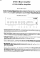
Product
Description
Th9
AT60 is
a 60
$€tt mixer
amplifier
and
similarly
the
ATl20
is
a
l2o
*ztt mixer
amplifier.
Both models
operate
on 240 VAC,
50
Hz
(or
I l0 VAC
with factory
modificauon)
and may
be desk
or rack mounted
via
an optional rack mount
kit.
Both amplifie6
incorporate
a 6 zone 100
volt
line
sfraker zone
selector with
all
call.
The
A,T60 will
deliver 60
watts into
a
load
of
g
otrms, ZO
or
100
volt line.
The
AT120
will
deliver 120 watts into
a
load
of
.l
or
8
ohms. 70
or
100
volt line. As
standard
both models
are self
standing
and
come with
rubber feet.
They may
be stacked
to a maximum
of four
units high.
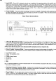
Front
Panel Controls
t. Dual
llicrophone/Line
Gain
Controls:
The +
duat mic/line
inpur
controls
are labelled
ch I
through
ro Ch 4
and should
be adjusted
to
provide
the rcquired
mix levet
for
each
individual
channel.
Start with
the controls
set to level 0
and
turn
the controls
clockwise
until the
desircd mix
level for
each
channel is reached"
Bass
Tonal
Control:
Sening this
contml in
the cente
position
will
give
an
overall flat
bass response
!o
the output
of
the amplifier'
Adjusting
the
bass control in
a clockwise
direction
will
provide
up ro 12
dB
of bass boo tt
q
rco ut.
Adjusting
the bass control
in
a counter-clockwise
direction
will
provide
up to
-12
dB
of bass o,tr
@
loo Hz.
Treble
Tonal
Control:
Setting
this control
in the
centre
position
will
give
an overall
flat treble
response
to the
output
of the amplifier.
Adjusting
&e Feble
control in
a clockwise
direction
will
provide
up
to
lo
dB
of rebt;
boosr
g
touiy.
Adjusting
the treble
control in
a counter-clockwise
direction
will
provide
up
to
-lO
dB of
treble cut
@
lO l'l]|z.
aster
Output
Control:
This
controls
the overall
output level
of the arnplifier
depending
on the levels
set for
the
individual
iryut
mir
channels
as detailed
above.
Start with
the control
s€t to
level
0 and
tum
clockwise until
the d€sired
output
level
of the amplifier
is reached
All Call
Button:
When
pressed,
this orange
button wilt
connect
the 100
volt output
of rhe
amplifier
to
all 6 of the
switched outFrts
of
the amplifier.
Depressing
this
button
again will
disconnect
the switcha
ofiputs. fnis
swiah is
,.push
on-
push
of' and is non-interlocking.
Speaker
Selector
Switches:
Thes€ 6
black
buttons are for
swirching
rhe 100
volr output
of the
amplifier
to any
combination
of fte 6
available speaker
zones.
The
switches
are'push
on-push
off'and are non-interlocking (boi6
with
eacir
other
and with
the all-call
button).
The maximum
capacity
of each slBaker
zone is 60
watts
so care
should
be taken
to ensure
that no individual
zone is
loaded
down
with
any morc than 60
watts,
always remembering
that
the total load
for the
AT60 is 60
watts in
total
and for the
ATl20, 120
watts
in total.
Eg; It is
pnssible
on
the ATl20, for
example,
to safely
have
one zone
loaded
with 60
watts
and the remaining
five loaded
with l2
wans
each.
3.
4.
5.
Ar 1
20
EuDionirft