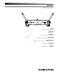
System 9 VHF Wireless System Installation and Operation 1 RF 2 3 CHANNEL 4 PEAK SYSTEM 9 ATW-901 UniPak® Transmitter System ATW-901/G Guitar System A R D FT ATW-901/H Headworn Microphone System ATW-901/H92 Miniature Headworn Microphone System ATW-901/H92-TH Miniature (beige) Headworn Microphone System ATW-901/L Lavalier Microphone System ATW-902 Handheld Microphone System
System 9 Installation and Operation This device complies with part 15 of the FCC Rules. Operation is subject to the condition that this device does not cause harmful interference. The ATW-R900 receiver includes a switching power supply that automatically adapts to changes in mains voltage. A copy of the declaration of conformity can be found on the internet at www.audio-technica.com.
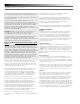
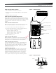
System 9 Installation and Operation Receiver Controls and Functions 1a 1b 2 3 1 RF 4 2 3 5 1 4 PEAK CHANNEL SYSTEM 9 Figure A — Front Panel Controls and Functions 1. ANTENNAS: Position the “signal” antenna (1a) and “ground” antenna (1b) as shown to the right and above right. Fully extend both antennas by pulling on the endcaps. 2. RF INDICATOR: Lights to show presence of transmitter signal. 3. CHANNEL SELECT BUTTON: Soft-touch button selects channel. 4.
System 9 Installation and Operation Transmitter Setup Controls and Functions Battery Selection and Installation Two alkaline AA batteries are recommended. When inserting the battery, observe correct polarity as marked inside the battery compartment.
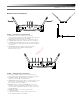
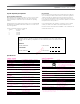
System 9 Installation and Operation UniPak® Transmitter Battery Installation 1. Slide off the battery cover as shown in Figure D. Figure D — UniPak® Transmitter Switch Configuration for Channel Selection 2. Carefully insert two fresh AA alkaline batteries, observing polarity markings. CHANNEL 1 CHANNEL 2 CHANNEL 3 CHANNEL 4 ON ON ON ON 1 3. Replace the battery cover (Fig. D).
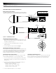
System 9 Installation and Operation System Operation Adjusting Input Level - Handheld Transmitter Unscrew the lower body cover and slide it off, exposing the screwdriver and "LEVEL" (Gain Trimmer) control (Fig. C). Remove the screwdriver from its clip. Gently turn the "LEVEL" control to its full clockwise position (toward the side marked “H”), the factory setting. Check for excessive gain by speaking/singing into the microphone at typically-loud levels while watching the receiver’s AF Peak indicator.
System 9 Installation and Operation System Operating Frequencies System Operating Frequencies Each transmitter/receiver system operates on a choice of four switchselected frequencies. Available frequencies are shown below. All frequencies may be combined for up to 4 simultaneous operating channels. RF Interference Please note that wireless frequencies are shared with other radio services.
System 9 Installation and Operation T F A DR Audio-Technica U.S., Inc. 1221 Commerce Drive, Stow, Ohio 44224 USA +1 (330) 686-2600 Audio-Technica Limited Old Lane, Leeds LS11 8AG England +44 (0) 113 277 1441 Audio-Technica (Greater China) Limited Unit K, 9/F., Kaiser Est. (Ph.2) 51 Man Yue St. Kowloon, HK. +852-2356-9268 Audio-Technica (S.E.A.) Pte. Ltd. No 1 Ubi View, #01-14 Focus One, Singapore 408555 +65-6749-5686 Audio-Technica Corporation 2206, Naruse Machida, Tokyo Japan ©2012 Audio-Technica U.S.