User's Guide Hammerfall® DSP System Multiface II The most compact professional multitrack recording system ever! ™ TotalMix 24 Bit / 96 kHz 9 ® SyncAlign ZLM ® ® SyncCheck PCI Busmaster Digital I/O System PCI and CardBus Interface 8 + 8 + 2 Channels Analog / ADAT / Stereo Interface Hi-Power Hi-End Headphone Output 24 Bit / 96 kHz
General 1 2 3 4 5 6 7 8 9 Introduction ...............................................................6 Package Contents .....................................................6 System Requirements ..............................................6 Brief Description and Characteristics.....................7 Hardware Installation 5.1 PCI Interface ...........................................................7 5.2 CardBus Card .........................................................7 5.3 Notes on Power Supply ..
Driver Installation and Operation - Mac OS X 19 Driver and Flash Update 19.1 Driver Installation ................................................. 36 19.2 Driver Update....................................................... 36 19.3 Flash Update........................................................ 36 20 Configuring the Multiface II 20.1 Settings Dialog..................................................... 37 20.2 Clock Modes – Synchronization .......................... 39 21 Mac OS X FAQ 21.
29 TotalMix: The Matrix 29.1 Overview ..............................................................65 29.2 Elements of the Matrix View ................................65 29.3 Usage...................................................................65 29.4 Advantages of the Matrix .....................................66 30 TotalMix Super-Features 30.1 ASIO Direct Monitoring (Windows only) ..............66 30.2 Selection and Group based Operation ................67 30.3 Copy Routings to other Channels ......
User's Guide Multiface II General User's Guide HDSP System Multiface II © RME 5
1. Introduction Thank you for choosing the RME Hammerfall DSP system. This unique audio system is capable of transferring analog and digital audio data directly to a computer from practically any device. The latest Plug and Play technology guarantees a simple installation, even for the inexperienced user. The numerous unique features and well thought-out configuration dialog puts the Hammerfall DSP at the very top of the range of computer-based audio interfaces.
4. Brief Description and Characteristics • • • • • • • • • • • • • • • • Hammerfall design: 0% (zero!) CPU load, even using all 36 ASIO channels All settings can be changed in real-time Analog, ADAT and SPDIF I/Os can be used simultaneously 8 buffer sizes/latencies available: 1.
5.3 Notes on Power Supply • The CardBus card delivers no power to the Multiface. Therefore a hi-tech switching power supply is included. • The PCI card operates as power supply for the attached Multiface via the FireWire cable. An external power supply is not required. The Multiface II draws a high startup current of more than 2 A during initialisation. Current at 12 Volt operating voltage: unloaded 720 mA (8.6 Watts), loaded 1 A (12 Watts). Supply voltage range DC 8 V – 28 V, AC 8 V – 20 V.
The rear panel of the Multiface II has eight analog inputs and outputs, the Power socket (only necessary with CardBus operation), Word Clock input and output, and both digital inputs and outputs ADAT and SPDIF. ADAT I/O (TOSLINK): Can also be used as optical SPDIF input and output, if set up accordingly in the Settings dialog. The Settings dialog is started by clicking on the hammer symbol in the Task Bar's system tray.
6.3 Notes on Laptops and CardBus The HDSP system uses the notebook’s PCMCIA type II port as CardBus interface. Compared to a PC-Card, which only has access to the outdated ISA-bus, CardBus is a 32 bit PCI interface. Like with a desktop system it’s not possible to remove a PCI device while in operation. First the operating system has to receive a ‚removal request’, then the device has to be stopped. Finally the card can be pulled out of the PCMCIA slot.
7. Accessories RME offers several optional accessories. Additionally parts of the HDSP system are available separately. Part Number 36000 Description 19“, 1UH Universal rack holder This 19" rack holder has holes for Digiface and Multiface. Two units can be installed side by side in any combination. The rack holder also includes holes for nearly all 19" half-rack units from other manufacturers. 36001 36002 36005 36010 Firewire cable IEEE1394 6M/6M, 1 m (3.3 ft) Firewire cable IEEE1394 6M/6M, 3 m (9.
8. Warranty Each individual Hammerfall DSP undergoes comprehensive quality control and a complete test at IMM before shipping. The usage of high grade components allow us to offer a full two year warranty. We accept a copy of the sales receipt as valid warranty legitimation. If you suspect that your product is faulty, please contact your local retailer.
CE / FCC Compliance CE This device has been tested and found to comply with the limits of the European Council Directive on the approximation of the laws of the member states relating to electromagnetic compatibility according to RL89/336/EWG and RL73/23/EWG. FCC This equipment has been tested and found to comply with the limits for a Class B digital device, pursuant to Part 15 of the FCC Rules.
User's Guide HDSP System Multiface II © RME
User's Guide Multiface II Driver Installation and Operation - Windows User's Guide HDSP System Multiface II © RME 15
10. Driver and Firmware 10.1 Driver Installation After the interface has been installed correctly, connected to the Multiface (see 5. Hardware Installation), and the computer has been switched on, Windows will recognize the new hardware component and start its ‘Hardware Wizard’. Insert the RME Driver CD into your CD-ROM drive, and follow further instructions which appear on your computer screen. The driver files are located in the directory \WDM on the RME Driver CD.
10.4 Firmware Update The Flash Update Tool updates HDSP PCI cards or CardBus cards to the latest version. It requires an already installed driver. Start the program hdsp_fut.exe or hdsp_pcie_fut.exe. The Flash Update Tool displays the current revision of the HDSP interface, and whether it needs an update or not. If so, then please manually select if a PCI card (desktop computer) or a CardBus card (laptop) shall be flashed. Next simply press the 'Update' button.
11. Configuring the Multiface II 11.1 Settings Dialog Configuration of the HDSP system Multiface is done via its own settings dialog.
WDM SyncAlign guarantees synchronous channels when using MME multitrack software. This option should only be switched off in case the used software does not work correctly with SyncAlign activated. With Interleaved activated, WDM devices can be used as 8-channel devices (see chapter 12.4). Buffer Size The setting Buffer Size determines the latency between incoming and outgoing ASIO and GSIF data, as well as affecting system stability (see chapter 13/14).
I/O Box State This field displays the current state of the I/O-box. Error: I/O-box not connected or missing power Detected: The interface has found an I/O-box and tries to load the firmware Connected: Communication between interface and I/O-box operates correctly Disconnected: Communication between interface and I/O-box has been interrupted, I/O-box continues operation Word Clock Out The word clock output signal usually equals the current sample rate.
The Hammerfall DSP's ADAT optical input and the SPDIF input operate simultaneously. Because there is no input selector however, the HDSP has to be told which of the signals is the sync reference (a digital device can only be clocked from a single source). This is why the system has been equipped with automatic clock source selection, which adopts the first available input with a valid digital signal as the clock reference input.
12. Operation and Usage 12.1 Playback The HDSP system can play back audio data only in supported modes (channels, PCM) and formats (sample rate, bit resolution). Otherwise an error message appears (for example at 22 kHz and 8 bit). In the audio application being used, HDSP must be selected as output device. This can often be found in the Options, Preferences or Settings menus under Playback Device, Audio Devices, Audio etc. We strongly recommend switching off all system sounds (via >Control Panel /Sounds<).
12.2 DVD-Playback (AC-3/DTS) under MME AC-3 / DTS When using popular DVD software player like WinDVD and PowerDVD, their audio data stream can be sent to any AC-3/DTS capable receiver, using the Hammerfall DSP's SPDIF output. For this to work the SPDIF output wave device has to be selected in >Control Panel/ Sounds and Multimedia/ Audio<. Also check 'use preferred device only'. You will notice that the DVD software's audio properties now allow to use 'SPDIF Out', 'Use SPDIF' or to 'activate SPDIF output'.
12.3 Notes on WDM The driver offers a WDM streaming device per stereo pair, like HDSP Multiface (1+2). WDM streaming is Microsoft's current driver and audio system, directly embedded into the operating system. WDM streaming is nearly unusable for professional music purposes, as all data is processed by the so called Kernel Mixer, causing a latency of at least 30 ms.
12.4 Multi-client Operation RME audio interfaces support multi-client operation. This means several programs can be used at the same time. Also all formats, like ASIO, WDM and GSIF can be used simultaneously. The use of multi-client operation requires to follow two simple rules: • Multi-client operation requires identical sample rates! I.e. it is not possible to use one software with 44.1 kHz and the other with 48 kHz. • Different software can not use the same channels at the same time.
12.5 Digital Recording Unlike analog soundcards which produce empty wave files (or noise) when no input signal is present, digital I/O cards always need a valid input signal to start recording. To take this into account, RME included a comprehensive I/O signal status display (showing sample frequency, lock and sync status) in the Settings dialog, and status LEDs for each input. If a 48 kHz signal is fed to the input and the application is set to 44.1 kHz, Check Input stops the system from recording.
12.6 Analog Recording For recordings via the analog inputs the corresponding record device has to be chosen (HDSP Analog (x+x)). Apart from the three reference levels, the Multiface has no means to change the input level. This would make no sense for the digital inputs, but also for the analog inputs one can do without it.
When using more than one HDSP system, all units have to be in sync, see chapter 15. Else a periodicly repeated noise will be heared. Another common source of trouble is incorrect synchronization. ASIO does not support asynchronous operation, which means that the input and output signals not only have to use the same sample frequency, but also have to be in sync. All devices connected to the Hammerfall DSP must be properly configured for Full Duplex operation.
15. Using more than one Hammerfall DSP The current drivers support operation of up to three Hammerfall DSP systems. Different I/Oboxes may be used, in any combination. Multiface, Multiface II, Digiface, HDSP 9632 and HDSP 9652 use the same driver, therefore can be used at the same time. Please note that only one ADAT Sync In can be used (of course). All units have to be in sync, i.e. have to receive valid sync information either via word clock or by using AutoSync and feeding synchronized signals.
17. Hotline – Troubleshooting 17.1 General The newest information can always be found on our website www.rme-audio.com, section FAQ, Latest Additions. The input signal cannot be monitored in real-time • ASIO Direct Monitoring has not been enabled, and/or monitoring has been disabled globally. The 8 ADAT channels don’t seem to work • The optical output has been switched to SPDIF. The ADAT playback devices are still usable by routing and mixing them in TotalMix to other outputs.
17.2 Installation Hammerfall DSP is found in the Device Manager (>Settings/ Control Panel/ System<), category 'Sound-, Video- and Gamecontroller'. A double click on ' Hammerfall DSP ' starts the properties dialog. Choosing 'Resources' shows Interrupt and Memory Range. The newest information on hardware problems can always be found on our website www.rmeaudio.com, section FAQ, Hardware Alert: about incompatible hardware.
18. Diagrams 18.1 Channel Routing ASIO at 96 kHz This diagram shows the signal paths in ASIO double speed mode (88.2 / 96 kHz). The devices available via the ASIO driver have been designed to avoid conflicts in normal operation. Record and playback are identical.
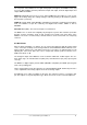
18.2 Channel Routing WDM at 96 kHz This diagram shows the signal paths in MME double speed mode (88.2 / 96 kHz). The devices available via the MME wave driver have been designed to avoid conflicts in normal operation, which is why channels 5, 6, 7 and 8 of the ADAT device have been omitted. Record and playback are identical.
User's Guide HDSP System Multiface II © RME
User's Guide Multiface II Driver Installation and Operation – Mac OS X User's Guide HDSP System Multiface II © RME 35
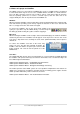
19. Driver and Flash Update 19.1 Driver Installation First fit the card (see 5. Hardware Installation), then switch on the computer and install the drivers from the RME Driver CD. The driver file is located in the folder Hammerfall DSP. Installation works automatically by a double-click on the file hdsp.mpkg. RME recommends to download the latest driver version from the RME website! If done, the procedure is as follows: Double-click onto hdsp_xx.gz to expand the archive2.
All other PCI cards, and CardBus with 15-pin flat connector When the update fails (status: failure) the flash process should be repeated several times, until no error message occurs anymore. If the failure message is displayed nonetheless, the interface will most propably no longer work when the computer is switched off and on again. The interface then has to be re-programmed at the factory. We have invested a lot of work to prevent the system from getting in this state.
SPDIF In Defines the input for the SPDIF signal. 'Coaxial' relates to the RCA socket, 'Optical' to the optical TOSLINK input. SPDIF Out The SPDIF output signal is constantly available at the phono plug. After selecting 'Optical' it is also routed to the optical TOSLINK output. For further details about the settings ‘Professional’, ‘Emphasis’ and ‘Non-Audio’, please refer to chapter 26.2. SPDIF Freq. Displays the sample rate of the signal at the SPDIF input.
System Clock Shows the current clock state of the HDSP system. The system is either Master (using its own clock) or Slave (see AutoSync Ref). SyncCheck SyncCheck indicates whether there is a valid signal (Lock, No Lock) for each input (Word Clock, ADAT, SPDIF), or if there is a valid and synchronous signal (Sync). The AutoSync Reference display shows the input and frequency of the current sync source. 20.
If several digital devices are to be used simultaneously in a system, they not only have to operate with the same sample frequency but also be synchronous with each other. This is why digital systems always need a single device defined as ‘master’, which sends the same clock signal to all the other (‘slave’) devices. RME’s exclusive SyncCheck technology (first implemented in the Hammerfall) enables an easy to use check and display of the current clock status.
21. Mac OS X FAQ 21.1 Round about Driver Installation The driver with the file suffix gz provided by RME is a compressed TAR archive. TAR bundles multiple files and folders into one file, but does not save memory space nor download time. Both TAR and gz are supported natively by OS X, a double click on the file is all you need to do. Older browsers do not recognize gz as an archive, loading the file as a document. This results in a cryptic looking text within the browser window.
21.3 Supported Sample Rates RME's Mac OS X driver supports all sampling frequencies provided by the hardware. Besides 96 kHz this also includes 32 kHz and 64 kHz. But not every software will support all the hardware's sample rates. For example Spark does not display 32 kHz and 64 kHz. The hardware's capabilities can easily be verified in the Audio MIDI Setup. Select Audio devices under Properties of: and choose the Hammerfall DSP. A click on Format will list the supported sample frequencies.
Multicard Operation OS X supports more than one audio device. Since 10.4 (Tiger) Core Audio offers the function Aggregate Devices, which allows to combine several devices into one, so that a multi-device operation is possible with any software. The Hammerfall DSP driver adds a number to each unit, so they are fully accessible in any multicard-capable software. 22. Hotline – Troubleshooting The newest information can always be found on our website www.rme-audio.com, section Support, Macintosh OS.
23. Diagram: Channel Routing at 96 kHz This diagram shows the signal paths in double speed mode (88.2 / 96 kHz). The last four channels of the ADAT port have no function anymore in Core Audio, but are used by the hardware to transmit data at double sample rate.
User's Guide Multiface II Disconnect Mode, Connections and TotalMix User's Guide HDSP System Multiface II © RME 45
24. Disconnect Mode RME's exclusive Disconnect mode lets you adjust level, input selection and signal mix via your computer, and simply detach the Multiface afterwards. With this, a stand-alone operation of the Multiface gets possible. When the Multiface has been configured using Settings dialog and TotalMix, it won't loose those settings after detaching it from the computer.
25.2 Line Outputs The eight short circuit protected, low impedance line outputs are available as 1/4" TRS jacks on the back of the unit. The electronic output stage is built in a servo balanced design which handles unbalanced (mono jacks) and balanced (stereo jacks) correctly.
26. Digital Connections 26.1 ADAT The ADAT optical input of the HDSP system is fully compatible with all ADAT optical outputs. RME's unsurpassed Bitclock PLL prevents clicks and drop outs even in extreme varipitch operation, and guarantees a fast and low jitter lock to the digital input signal. A usual TOSLINK cable is sufficient for connection. More information on Double Speed (S/MUX) can be found in chapter 34.3. ADAT In Interface for a device sending an ADAT signal to the Multiface.
The Multiface’s new output header is optimized for largest compatibility with other digital devices: • • • • • • • 32 kHz, 44.1 kHz, 48 kHz, 88.
27. Word Clock 27.1 Technical Description and Usage In the analog domain one can connect any device to another device, a synchronization is not necessary. Digital audio is different. It uses a clock, the sample frequency. The signal can only be processed and transmitted when all participating devices share the same clock. If not, the signal will suffer from wrong samples, distortion, crackle sounds and drop outs.
The word clock input of the Hammerfall DSP is a high-impedance type ensuring maximum flexibility, and is therefore not terminated. If normal termination is necessary (e.g. because Hammerfall DSP is the last device in the chain), simply connect a T-adapter to its BNC input jack, connect the cable supplying the word clock signal to one arm of the T-adapter and terminate the other with a 75 Ohm resistor (as a short BNC plug).
28. TotalMix: Routing and Monitoring 28.1 Overview The Multiface includes a powerful digital real-time mixer, the Hammerfall DSP mixer, based on RME’s unique, sample-rate independent TotalMix technology. It allows for practically unlimited mixing and routing operations, with all inputs and playback channels simultaneously, to any hardware outputs. Here are some typical applications for TotalMix: • Setting up delay-free submixes (headphone mixes).
User's Guide HDSP System Multiface II © RME 53
28.2 The User Interface The visual design of the TotalMix mixer is a result of its capability to route hardware inputs and software playback channels to any hardware output. The Multiface provides 18 input channels, 18 software playback channels, and 20 hardware output channels: 36 channels don't fit on the screen side by side, neither does such an arrangement provide a useful overview. The input channel should be placed above the corresponding output channel.
28.3 Elements of a Channel A single channel consists of various elements: Input channels and playback channels each have a mute and solo button. Below there is the panpot, realized as indicator bar (L/R) in order to save space. In the field below, the present level is displayed in RMS or Peak, being updated about every half a second. Overs (overload) are indicated here by an additional red dot. Next is the fader with a level meter.
You see, it is very easy to set up a specific submix for whatever output: select output channel, set up fader and pans of inputs and playbacks – ready! For advanced users sometimes it makes sense to work without Submix View. Example: you want to see and set up some channels of different submixes simultaneously, without the need to change between them all the time. Switch off the Submix View by a click on the green button.
You will certainly have noticed that the signal at the outputs 7/8 did not change while you were routing channel 4 to other outputs and setting different gain values for those. With all analog and most digital mixing desks, the fader setting would affect the level for every routed bus - not so for TotalMix. TotalMix allows for setting all fader values individually. Therefore the faders and the panpots jump to the appropriate setting as soon as another routing is chosen.
28.7 The Quick Access Panel This section includes additional options, further improving the handling of TotalMix. The Master buttons for Mute and Solo have already been described, they allow for group-based working with these functions. In the View section the single mixer rows can be made visible or invisible. If the inputs are not needed for a pristine playback mix, the whole upper row falls out of the picture after a click on the Input button.
Mouse: The original factory presets can be reloaded by holding down the Ctrlkey and clicking on any preset button. Alternatively the files described above can be renamed, moved to a different directory, or being deleted. Keyboard: Using Ctrl and any number between 1 and 8 (not on the numeric keypad!) will load the corresponding factory default preset. The key Alt will load the user presets instead. When loading a preset file, for example 'Main Monitor AN 1_2 plus headphone mix 3_4.
28.9 The Monitor Panel The Monitor panel provides several options usually found on analog mixing desks. It offers quick access to monitoring functions which are needed all the time in typical studio work. Monitor Main Use the drop down menu to select the hardware outputs where your main monitors are connected to. Dim A click on this button will lower the volume of your main monitor output (see above) by an amount set up in the Preferences dialog (see below).
Main Monitor Dim: Amount of attenuation of the Main Monitor output in dB. Activated by the Dim button in the Monitor panel. Stereo Pan Law The Pan Law can be set to -6 dB, -4.5 dB, -3 dB and 0 dB. The value chosen defines the level attenuation in pan center position. This setting is useful because the ASIO host often supports different pan laws too. Selecting the same value here and in the ASIO host, ASIO Direct Monitoring works perfectly, as both ASIO host and TotalMix use the same pan law.
28.12 Hotkeys In many situations TotalMix can be controlled quickly and comfortably by the keyboard, making the mixer setup considerably easier and faster. The Shift-key for the fine mode for faders and panpots has already been mentioned. The Ctrl-key can do far more than changing the routing pairwise: • Clicking anywhere into the fader area with the Ctrl-key pressed, sets the fader to 0 dB. • Clicking anywhere into the pan area with the Ctrl-key pressed, sets the panorama to meaning Center.
28.13 Menu Options Always on Top: When active (checked) the TotalMix window will always be on top of the Windows desktop. Note: This function may result in problems with windows containing help text, as the TotalMix window will even be on top of those windows, so the help text isn't readable. Deactivate Screensaver: When active (checked) any activated Windows screensaver will be disabled temporarily. Ignore Position: When active, the windows size and position stored in a file or preset will not be used.
28.14 Level Meter The Multiface II calculates all the display values Peak, Over and RMS in hardware, in order to be capable of using them independent of the software in use, and to significantly reduce the CPU load. Tip: This feature, the Hardware Level Meter, is used by DIGICheck (Windows only, see chapter 16) to display Peak/RMS level meters of all channels, nearly without any CPU load. The level meters integrated in TotalMix - considering their size - cannot be compared with DIGICheck.
29. TotalMix: The Matrix 29.1 Overview The mixer window of TotalMix looks and operates similar to mixing desks, as it is based on a conventional stereo design. The matrix display presents a different method of assigning and routing channels, based on a single channel or monaural design. The matrix view of the HDSP looks and works like a conventional patchbay, adding functionality way beyond comparable hardware and software soutions.
29.4 Advantages of the Matrix The Matrix not always replaces the mixer view, but it significantly enhances the routing capabilities and - more important - is a brilliant way to get a fast overview of all active routings. It shows you in a glance what's going on. And since the Matrix operates monaural, it is very easy to set up specific routings with specific gains.
30.2 Selection and Group-based Operation Click on the white name label of channel 1 and 2 in TotalMix. Be sure to have channel 3's fader set to a different position and click on its label too. All three labels have changed to the colour orange, which means they are selected. Now moving any of these faders will make the other faders move too. This is called 'building a group of faders', or ganging faders, maintaining their relative position.
30.5 Recording a Subgroup (Loopback) TotalMix supports a routing of the subgroup outputs (=hardware outputs, bottom row) to the recording software. Instead of the signal at the hardware input, the signal at the hardware output is sent to the record software. This way, complete submixes can be recorded without an external loopback cable. Also the playback of a software can be recorded by another software. To activate this function, click on the white label in the third row while holding down the Ctrl-key.
Recording a Software's playback In real world application, recording a software's output with another software will show the following problem: The record software tries to open the same playback channel as the playback software (already active), or the playback one has already opened the input channel which should be used by the record software. This problem can easily be solved.
Unfortunately, very often it is not possible within the record software to assign a different input channel to an existing track 'on the fly'. The loopback mode solves this problem elegantly. The routing scheme stays the same, with the input channel 10 sent to any output via TotalMix, to the Compressor, from the Compressor back to any input. Now this input signal is routed directly to output 10, and output 10 is then switched into loopback mode via Ctrl-mouse. As explained in chapter 30.
31.3 Setup • Open the Preferences dialog (menu Options or F3). Select the MIDI Input and MIDI Output port where your controller is connected to. • When no feedback is needed (when using only standard MIDI commands instead of Mackie Control protocol) select NONE as MIDI Output. • Check Enable MIDI Control in the Options menu. 31.4 Operation The channels being under MIDI control are indicated by a colour change of the info field below the faders, black turns to yellow.
31.5 Simple MIDI Control The stereo output faders (lowest row) which are set up as Monitor Main outputs in the Monitor panel can also be controlled by the standard Control Change Volume via MIDI channel 1. With this, the main volume of the Multiface is controlable from nearly any MIDI equipped hardware device. Even if you don't want to control all faders and pans, some buttons are highly desired to be available in 'hardware'.
Examples for sending MIDI strings*: - Set input 1 to 0 dB: B0 66 40 - Set input 17 to maximum attenuation: B1 66 0 - Set playback 1 to maximum: B4 66 7F - Set Output 16 to 0 dB setzen B8 75 40 *Note: Sending MIDI strings might require to use programmer's logic for the MIDI channel, starting with 0 for channel 1 and ending with 15 for channel 16. 31.6 Loopback Detection The Mackie Control protocol requires feedback of the received commands, back to the hardware controller.
User's Guide HDSP System Multiface II © RME
User's Guide Multiface II Technical Reference User's Guide HDSP System Multiface II © RME 75
32. Tech Info Not all information to and around our products fit in a manual. Therefore RME offers a lot more and detailed information in the Tech Infos. The very latest Tech Infos can be found on our website, section News & Infos, or the directory \rmeaudio.web\techinfo on the RME Driver CD. These are some of the currently available Tech Infos: Synchronization II (DIGI96 series) Digital audio synchronization - technical background and pitfalls. Installation problems - Problem descriptions and solutions.
33. Technical Specifications 33.1 Analog AD • Resolution: 24 bit • Signal to Noise ratio (SNR): 107.5 dB RMS unweighted, 111.5 dBA • THD: < -100 dB, < 0.001 % • THD+N: < -98 dB, < 0.0012 % • Channel separation: > 100 dB • Frequency response AD @ 44.1 kHz, -0.5 dB: 5 Hz – 21.0 kHz • Frequency response AD @ 96 kHz, -0.5 dB: 5 Hz – 45.3 kHz • Input: 6.
33.3 Digital Inputs SPDIF - AES/EBU • 1 x RCA, transformer-balanced, galvanically isolated, according to AES3-1992 • High-sensitivity input stage (< 0.
33.6 General • • • • • • • • • • Power supply: external switching power supply, 100 - 240 V AC, 15 Watt Current at 12 Volt operating voltage, unloaded: 720 mA (8.6 Watt) Current at 12 Volt operating voltage, loaded: 1 A (12 Watt) Typical power consumption: 12 Watt Voltage range: DC 8 V – 28 V, AC 8 V – 20 V Dimensions including rack ears (WxHxD): 265 x 44 x 165 mm (10.5" x 1.73" x 6.5") Dimensions without rack ears/handles (WxHxD): 218 x 44 x 155 mm (8.6" x 1.73" x 6.1") Weight: 1.5 kg ( 3.
34.2 Latency and Monitoring The term Zero Latency Monitoring has been introduced by RME in 1998 for the DIGI96 series of audio cards. It stands for the ability to pass-through the computer's input signal at the interface directly to the output. Since then, the idea behind has become one of the most important features of modern hard disk recording.
Note: Cubase and Nuendo display the latency values signalled from the driver separately for record and playback. While with our former cards these values equalled exactly the buffer size (for example 3 ms at 128 samples), the Multiface displays an additional millisecond – the time needed for the AD/DA-conversion. Core Audios Safety Offset Under OS X, every audio interface has to use a so called satety offset, otherwise Core Audio won't operate click-free. The Multiface uses a safety offset of 32 samples.
34.4 AES/EBU - SPDIF The most important electrical properties of 'AES' and 'SPDIF' can be seen in the table below. AES/EBU is the professional balanced connection using XLR plugs. The standard is being set by the Audio Engineering Society based on the AES3-1992. For the 'home user', SONY and Philips have omitted the balanced connection and use either Phono plugs or optical cables (TOSLINK). The format called S/P-DIF (SONY/Philips Digital Interface) is described by IEC 60958.
35. Diagrams 35.
35.2 Connector Pinouts TRS jacks of analog input / output The stereo ¼" TRS jacks of the analog inputs and outputs are wired according to international standards: Tip = + (hot) Ring = – (cold) Sleeve = GND The servo balanced input and output circuitry allows to use monaural TS jacks (unbalanced) with no loss in level. This is the same as when using a TRS-jack with ring connected to ground. TRS Phones jack The analog monitor output on the front is accessible through a stereo ¼" TRS jack.