
Specifications


Audio International, Inc. ASP-101-02-x Installation & Operation
Document #540183, Rev IR, 6/2000 Page 10 of 14
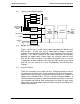
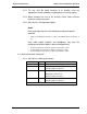
3.7 Pinout Assignments and Descriptions
P1 Pinout Chart
Pin # Description Pin # Description
1 +28 VDC Input (Digital) 20 Left Analog Audio Output High
2 Ground Input 21 Left Analog Audio Output Low
3 Data Bus A 22 Left Analog Audio Output Shield
4 Data Bus B 23 Right Analog Audio Output High
5 Data Bus Shield 24 Right Analog Audio Output Low
6 Unit ID 1 25 Right Analog Audio Output Shield
7 Unit ID 2 26 Front Left Output High
8 Unit ID 4 27 Front Left Output Low
9 ID Common 28 Front Right Output High
10 PA Key Input 29 Front Right Output Low
11 PA Audio High Input 30 Rear Left Output High
12 PA Audio Low Input 31 Rear Left Output Low
13 PA Audio Shield Input 32 Rear Right Output High
14 Left Analog Audio Input High 33 Rear Right Output Low
15 Left Analog Audio Input Low 34 Woofer Output High
16 Left Analog Audio Input Shield 35 Woofer Output Low
17 Right Analog Audio Input High 36 Center Output High
18 Right Analog Audio Input Low 37 Center Output Low
19 Right Analog Audio Input Shield
Connector Functions P2 – P13
P2 Optical Input #1 P8 Optical Input #4
P3 Optical Output #1 P9 Optical Output #4
P4 Optical Input #2 P10 Optical Input (for Analog Out)
P5 Optical Output #2 P11 Optical Output
P6 Optical Input #3 P12
Fiberlink Input
P7 Optical Output #3 P13
Fiberlink Output
3.8 Post Installation Test
3.8.1 With the aircraft power “ON”, select an audio source unit and
operate that unit to create audio signal to the ASP-101-02-x. Verify
that an audio output is present at one of the audio output locations.
Repeat this test for each audio source unit in the system. Repeat
this test for each audio output location in the system.
3.8.2 Repeat the above tests using all control units in the aircraft (switch
panels, IR Remotes, LCD touch-screen monitors, etc.)
3.8.3 Activate and speak into a microphone to verify that the PA audio
overrides the entertainment audio.