
Specifications

Audio International, Inc. ASP-101-02-x Installation & Operation
Document #540183, Rev IR, 6/2000 Page 9 of 14
3.5.3 The unit shall be rigidly mounted to its location using the
appropriate fastening hardware supplied by the installing agency.
3.5.4 When mounting the unit to the aircraft’s frame, allow sufficient
space for mating connectors.
3.5.5 ASP-101-02-x Configuration Options
Audio
Each audio input may have the following configuration options
specified:
• Input Level adjustment from 0% to 100% of full maximum in increments of
2%
Each audio output (amplifier and headphone) may have the
following configuration options specified independently:
• Power-up volume level from 0% to 80% in increments of 10%
• Power-up bass level from 0% to 100% in increments of 25%.
• Power-up treble level from 0% to 100% in increments of 25%.
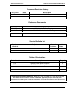
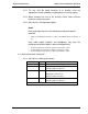
3.6 Mating Connector Information
3.6.1 ASP-101-02-x Mating Connectors
Model # Pin # Description
ASP-101-02-1 P1 RD37F10JVL0 Female Plug (Positronic)
P2-P13 Mates with ST Series Optical Cable
501380-2 AMP or Equivalent
ASP-101-02-2 P1 DCMA-37S Female Plug
M85049/48-1-4 Backshell
D20419-18 Male Screwlock
P2-P13 Mates with ST Series Optical Cable
501380-2 AMP or Equivalent
ALL CONNECTORS TO HAVE LOCK TAB SETS ON UNIT.