
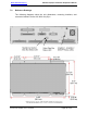
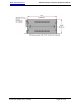
Specifications

Audio International, Inc. A/V-9691-01(-02)-x Installation & Operation Manual
Document # 540250, Rev D, 07/2004
Page 30 of 33
5.0 Troubleshooting
5.1 Introduction
Most functional problems are detected during the post installation test;
refer to Section 3.10, Post-Installation Test. Once the unit has passed
these tests, it can be functional for many years of service.
5.2 General Troubleshooting Procedures
• To verify power to the unit, recheck +28 VDC power is applied to the
proper pins on the unit. Use a voltmeter to verify correct level.
• Reset by removing power from the unit for at least one (1) minute and
reapply power.
• Recheck all connections to the unit for security. Check all harness
runs for possible pinching. Recheck all pinouts for application
accuracy.
• To check data bus integrity, utilizing a voltmeter, oscilloscope, or other
voltage instrument, verify proper input voltage on the data bus pins.
Typical measurements are as follows:
A to Ground : 4.0 to 4.5 VDC
B to Ground : 0.1 to 1.0 VDC
If any device is transmitting (i.e., holding bus active), then these typical
measurements would be reversed for the A-to-Ground and B-to-
Ground measurements. This troubleshooting tool can help indicate a
data bus lockup. If this occurs, remove the data bus from all other
equipment one piece at a time. As each is removed, check the bus
status to see if it is now functioning properly. Once you have removed
the piece or pieces of offending equipment, disconnect power and then
reconnect everything but the suspect component, reapply power and
test the functionality of the unit.
• The RS-485 data bus is a bi-directional bus that does not have a ‘bus
controller’. The bus uses a differential digital signal that will transmit
only when commands are entered via switch selection or other system
synchronizing commands. The “A” leg of the bus is HI and the “B” leg
LOW.