
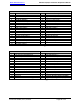
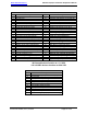
Specifications


Audio International, Inc. A/V-9691-01(-02)-x Installation & Operation Manual
Document # 540250, Rev D, 07/2004
Page 21 of 33
The first internal amplifier supplies audio output to the #1 amplifier
outputs. The second internal amplifier supplies audio output to the
#2 amplifier outputs. Via data bus configuration control, it is
possible to enable/disable the 135 Hz low-pass crossover for this
amplifier. This configuration determines whether or not the
amplifier outputs will be used to drive midrange/tweeter speaker
enclosures solely (split-cabin) or midrange/tweeter and subwoofer
speaker enclosures (bi-level).
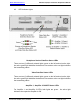
A ground stud connection is provided on the case of the unit to be
used as a ground bonding connection from this unit to aircraft
frame. A minimum of 10 AWG wiring is recommended. This
connection should be made to aircraft structure no more than 12
inches from the unit. The purpose of the ground stud connection is
two-fold. The first benefit is that this connection insures a proper
ground connection for the unit. The second benefit of this
connection is that it provides added stability for the amplifiers in this
unit in the event entertainment audio levels reach maximum
allowable limits to prevent amplifier overdriving and clipping.
Note: Amplifier outputs are designed to interface directly to
properly rated speakers only. Production wiring breaks
are acceptable provided the signal path remains intact,
uninterrupted, and electrically insulated. Any deviation
from this (including any intermediate signal switching)
is prohibited and may result in catastrophic failure of
the A/V-9691-01(-02)-x module as well as possible
damage to aircraft wiring and/or components.