
Specifications


Audio International, Inc. A/V-9691-01(-02)-x Installation & Operation Manual
Document # 540250, Rev D, 07/2004
Page 20 of 33
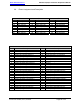
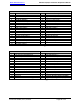
3.8.7 P10 Connector—The P10 connector provides for the last four (4)
audio output connections (C-F) from the A/V-9691-01(-02)-x. Each
audio output has connections provided for:
Left Channel High
Right Channel High
Audio Common
Pins 13-15 are provided for use when using a split-cabin
arrangement with a bi-level amplifier configuration for each cabin
zone. The audio output connections at these pins provide for audio
output directly from the second internal digital equalizer. These
connections are strictly reserved for connection to a second
external cabin audio amplifier module. These connections are
not to be used for connection to a headphone audio location.
If pins 13-15 are used, then pins 4-6 on the P6 connector are not to
be used and vice versa as these two (2) audio output locations are
tied together to the same internal audio control module.
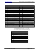
3.8.8 P12 Connector—The P12 connector provides for complete
chime/page capabilities. Refer to section 1.3.5 for additional
information regarding these features.
3.8.9 P13 Connector—The P13 connector provides for the following
connections:
• Power/ground input for amplifier and PA/chimes controls
• Amplifier #1 audio outputs (w/optional 135 Hz high pass
crossover)
• Amplifier #2 audio outputs (w/ optional 135 Hz low pass
crossover)
• Emergency power input
Pin L: Provides for emergency power input to power amplifiers and
PA/chimes controls during emergency conditions. Refer to Section
6.3.1 for additional information.
Each internal amplifier operates at 75 W
RMS into a 4 Ω load. It is
critical to maintain the 4 Ω load on each output channel to
avoid noise from the amplifier. Any variation above or below the
specified load might cause noise from the amplifier due to the
nature of the Class D amplifier used for each internal amplifier.
This variation can also effectively decrease the output power of the
amplifier.