
Specifications


Audio International, Inc. A/V-9691-01(-02)-x Installation & Operation Manual
Document # 540250, Rev D, 07/2004
Page 18 of 33
3.8 Overview of Electrical Characteristics
3.8.1 P1 Connector—The P1 connector provides for all video input
connections to the A/V-9691-01(-02)-x.
3.8.2 P2 Connector—The P2 connector provides for the first eight (8)
video output connections from the A/V-9691-01(-02)-x.
3.8.3 P3 Connector—The P3 connector provides for the second eight
(8) video output connections from the A/V-9691-01(-02)-x.
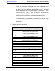
3.8.4 P5 Connector—The P5 connector provides for all eight (8) audio
input connections to the A/V-9691-01(-02)-x. Each audio input has
connections provided for:
Left Channel High Right Channel High
Left Channel Low Right Channel Low
Left Channel Shield Right Channel Shield
Audio Input Specifications
Optimum 4.7 kΩ @ 2 VRMS (Differential)
Minimum 4.7 kΩ @ 1 VRMS (Differential)
A KEY connection is provided to prevent misconnection between
the P5 connector and the P12 connector. This mechanical KEY
feature is intended to allow for insertion of a blanking pin to prevent
connection of the P12 connector
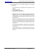
3.8.5 P6 Connector—The P6 connector provides for the first twelve (12)
audio output connections (0-B) from the A/V-9691-01(-02)-x. Each
audio output has connections provided for:
Left Channel High
Right Channel High
Audio Common
Pins 1-3 are reserved for internal use only. These connections
are not to be used when planning for audio output connections
to headphone panel locations.
Pins 4-6 are not to be used if the internal amplifiers are
configured for split-cabin operation during configuration of the
module.