Installation & Operation Manual A/V-9691-01(-02)-x Audio/Video Distribution Unit Document # 540250 a DeCrane Aircraft Company 7300 Industry Drive, North Little Rock, AR 72117 Phone: 501-955-2929 Fax: 501-955-2988 www.audiointl.
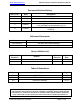
Audio International, Inc. A/V-9691-01(-02)-x Installation & Operation Manual Document Revision History Rev. Level Date Description IR 02/2003 Initial Release A 05/2003 Corrected Pinout B 11/2003 Corrected Grounding Requirements (p13) C 04/2004 Amended Wiring Requirements (sections 3.4.1 and 3.4.2) and data bus characteristics (3.6.
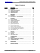
Audio International, Inc. A/V-9691-01(-02)-x Installation & Operation Manual Table of Contents Section 1.0 1.1 1.2 1.3 1.4 Description General Information . . . . . . . . . . . . . . . . . . . . . . . . . . . . . Introduction . . . . . . . . . . . . . . . . . . . . . . . . . . . . . . . . . . . . . Purpose of the Equipment . . . . . . . . . . . . . . . . . . . . . . . . . . Operational Features . . . . . . . . . . . . . . . . . . . . . . . . . . . . . . Optional Equipment . . . . . . . . . . . . . . . .
Audio International, Inc. A/V-9691-01(-02)-x Installation & Operation Manual A/V-9691-01(-02)-x Audio/Video Distribution Unit 1.0 General Information 1.1 Introduction This manual contains basic guidelines and information for the installation and operation of the Audio International, Inc. (AI), Audio/Video Distribution Unit, Model Number A/V-9691-01(-02)-x. The “-x” suffix in the model number designates the type of connector utilized; ”-1” = Positronic and “-2” = D-Subminiature.
Audio International, Inc.
Audio International, Inc. 2.0 A/V-9691-01(-02)-x Installation & Operation Manual Application 2.1 Introduction 2.1.1 The A/V-9691-01(-02)-x typically interfaces to various source equipment and audio signal manipulation devices. This unit is capable of interfacing and accepting input from all Audio International and standard COTS (Commercial-Off-The-Shelf) audio source equipment including but not limited to: CD, Cassette, DVD, and Videocassette players.
Audio International, Inc. A/V-9691-01(-02)-x Installation & Operation Manual 2.1.6 The A/V-9691-01(-02)-x allows up to eight (8) video inputs and 16 video outputs. These video outputs allow the distribution unit to display multiple video inputs on separate monitors independently. 2.1.7 The A/V-9691-01(-02)-x is equipped with a video briefer key input. This source is configurable via the RS-485 data bus. Power up default video selection is configurable for each video output.
Audio International, Inc. A/V-9691-01(-02)-x Installation & Operation Manual Audio Briefer Input: One (1) audio briefer input is provided to allow for broadcast of briefing messages from either the cockpit or an external device. The PTT input is ground active (<1.2 VDC to activate). Configurable audible tone activation for the audio briefer PTT activation allows either an ON tone and/or an OFF tone when the PTT input is activated and/or deactivated.
Audio International, Inc. A/V-9691-01(-02)-x Installation & Operation Manual High-Tone Chime Inputs: Two (2) high-tone chime inputs are provided for use. Each initiation will cause a single high tone activation. The high-tone chime feature activates both PA/chime key outputs when activated. High-tone input #1 is ground active (<1.2 VDC to activate). High-tone input #2 is +28 VDC active. Low-Tone Chime Inputs: Two (2) low-tone chime inputs are provided for use.
Audio International, Inc. A/V-9691-01(-02)-x Installation & Operation Manual PA/Chime Priority Hierarchy: The following lists the audio input priorities internal to the PA/chime functionality of the A/V-9691-01(-02)-x unit.
Audio International, Inc. 2.
Audio International, Inc. 3.0 A/V-9691-01(-02)-x Installation & Operation Manual Installation 3.1 Prior to Installation The A/V-9691-01(-02)-x is a simple module to install. Prior to installation, select a mounting location for the distribution unit. Mounting locations may include inside a credenza, an entertainment cabinet, a radio rack, or similar area. Refer to Section 7.0, Reference Drawings, for unit dimensions, mounting locations, and connector locations.
Audio International, Inc. 3.3 A/V-9691-01(-02)-x Installation & Operation Manual Cautions and Warnings 3.3.1 It is important to do a pin-to-pin power and ground check on all connectors. Ensure that power and ground are applied only where specified. Damage to the unit may result if power or ground is applied to the wrong points. 3.3.2 Perform a pin-to-pin check to confirm that the wiring terminates in the proper location. Ensure that there is only power and ground where required. 3.3.
Audio International, Inc. 3.4 A/V-9691-01(-02)-x Installation & Operation Manual Wiring Requirements The installing agency shall supply and fabricate all external cables and connectors. The length and routing of external cables should be carefully studied and planned before attempting installation of the equipment. Allow adequate space for installation of cable and connectors. 3.4.1 Power Wires All power and ground connections of P7 must be 20 AWG, MINIMUM.
Audio International, Inc. A/V-9691-01(-02)-x Installation & Operation Manual 3.4.3 Video Wires Composite video connections shall be shielded coaxial cable in accordance with M17/94-RG179 or equivalent. 3.4.4 RS-485 Data Bus Wires The A/V-9691-01(-02)-x is designed to interface with other Audio International equipment via AI’s proprietary RS-485 serial data bus. The data bus shall be implemented using a twisted shielded pair cable in accordance with NEMA WC 27500 or equivalent.
Audio International, Inc. 3.6 A/V-9691-01(-02)-x Installation & Operation Manual Electrical Characteristics 3.6.1 Electrical Specifications: Electrical Audio Power (P13-A) 12 Amp max @ +28 VDC Power (P7-1) 2 Amp max @ +28 VDC Emergency power (P13-L) 6 Amp max @ +28 VDC Operating Range +18 to +32 VDC, +28 VDC Nominal 8 Stereo Inputs 1 to 5 VRMS @ 4.
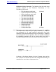
Audio International, Inc. A/V-9691-01(-02)-x Installation & Operation Manual 3.6.2 RS-485 Data bus Characteristics The Audio/Video Distribution Unit is designed to interface with other AI equipment via AI’s proprietary RS-485 digital data bus. This is a bi-directional data bus that allows multiple units to be connected simultaneously. All RS-485 data bus lines must be daisy-chained between units. Maximum allowable number of data bus nodes per data bus segment is 32 nodes.
Audio International, Inc. A/V-9691-01(-02)-x Installation & Operation Manual Finally, the access port connection needs to be in the main cabin area where it is easily accessible so that system configuration may be done in the main cabin to allow for audio levels to be heard during adjustments after interior installation is completed.
Audio International, Inc. 3.8 A/V-9691-01(-02)-x Installation & Operation Manual Overview of Electrical Characteristics 3.8.1 P1 Connector—The P1 connector provides for all video input connections to the A/V-9691-01(-02)-x. 3.8.2 P2 Connector—The P2 connector provides for the first eight (8) video output connections from the A/V-9691-01(-02)-x. 3.8.3 P3 Connector—The P3 connector provides for the second eight (8) video output connections from the A/V-9691-01(-02)-x. 3.8.
Audio International, Inc. A/V-9691-01(-02)-x Installation & Operation Manual 3.8.6 P7 Connector—The P7 connector provides for the following connections: • • • • Power/ground input for all headphone audio controls and video controls Data bus connections Unit ID strapping connections Video briefer key input connection Pins 6,7,9: The unit ID strapping connections provide for multiple A/V-9691-01(-02)-x units to be installed within the same data bus system.
Audio International, Inc. A/V-9691-01(-02)-x Installation & Operation Manual 3.8.7 P10 Connector—The P10 connector provides for the last four (4) audio output connections (C-F) from the A/V-9691-01(-02)-x. Each audio output has connections provided for: Left Channel High Right Channel High Audio Common Pins 13-15 are provided for use when using a split-cabin arrangement with a bi-level amplifier configuration for each cabin zone.
Audio International, Inc. A/V-9691-01(-02)-x Installation & Operation Manual The first internal amplifier supplies audio output to the #1 amplifier outputs. The second internal amplifier supplies audio output to the #2 amplifier outputs. Via data bus configuration control, it is possible to enable/disable the 135 Hz low-pass crossover for this amplifier.
Audio International, Inc. A/V-9691-01(-02)-x Installation & Operation Manual 3.8.
Audio International, Inc.
Audio International, Inc. A/V-9691-01(-02)-x Installation & Operation Manual 3.8.11 A/V-9691-01(-02)-x Order of Audio Adjustments The order of audio adjustments for the A/V-9691-01(-02)-x module is critical to the audio performance of the system (both cabin audio and headphone audio). The overall objective should be to maximum system gain while minimizing noise introduction. That is to say, the main goal in audio adjustment of the A/V-9691-01(-02)-x system is to maximize signal-to-noise ratios.
Audio International, Inc. 3.
Audio International, Inc.
Audio International, Inc.
Audio International, Inc. 3.10 A/V-9691-01(-02)-x Installation & Operation Manual Post-Installation Test Check all entertainment units for proper RS-485 data bus connections. Ensure the Audio/Video Distribution Unit is interfaced with the data bus. All control units that are installed in the aircraft should be tested for proper operation (i.e. Switch Panels, Hand-Held Remote Controls, and Touch Screen LCD Monitors). Use one (1) of these control units to activate an entertainment audio function.
Audio International, Inc. 4.3 A/V-9691-01(-02)-x Installation & Operation Manual LED Indicator Lights Headphone Section Data Bus Status LEDs There are two (2) differently colored lights; green on the left and red on the right. An active green light indicates the data bus flow and an active red light indicates the transmitting status. Video Data Bus Status LEDs There are two (2) differently colored lights; green on the left and red on the right.
Audio International, Inc. 5.0 A/V-9691-01(-02)-x Installation & Operation Manual Troubleshooting 5.1 Introduction Most functional problems are detected during the post installation test; refer to Section 3.10, Post-Installation Test. Once the unit has passed these tests, it can be functional for many years of service. 5.2 General Troubleshooting Procedures • • • • To verify power to the unit, recheck +28 VDC power is applied to the proper pins on the unit. Use a voltmeter to verify correct level.
Audio International, Inc. 5.3 A/V-9691-01(-02)-x Installation & Operation Manual Troubleshooting Chart Problem Possible Cause Audio is not present in the speakers and/or headphones. Video is not present on the monitor. Audio or video equipment is not operating properly. Solution Unit is not properly connected to the audio sources(s). • Ensure the unit has been properly connected to the audio source(s). Circuit breaker has been tripped. • Reset circuit breaker.
Audio International, Inc. 7.0 A/V-9691-01(-02)-x Installation & Operation Manual Reference Drawings The following diagrams show the unit dimensions, mounting locations, and connector locations for the A/V-9691-01(-02)-x.
Audio International, Inc.