
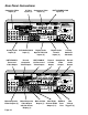
Audio Video Surround Sound Preamplifier Installation Manual


Page 16
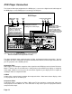
DVR/PVR Connection
The Out of the Box input configuration for a DVR (Digital Video Recorder) are sometimes called PVRs
(Personal Video Recorders). There are several different models available and the diagram below
shows connection of the most basic type of models.
These units feature analog audio outputs along with both composite video and S-Video outputs. The
diagram to the right details the connection of more advanced models that in addition to the outputs
found on standard models, also include a digital audio output as well as a VGA video output. Because
the Cinema Reference Mach II’s Out of the Box setup is designed for easy connection of all types of
DVRs, the diagram below shows the more basic connection. To alter the Cinema Reference’s input
configuration for DVR’s with digital audio, follow the instructions on the next page.
DVRs are designed to record material that is being broadcast (either off-air TV, cable TV, or DSS TV)
and may require an output from a broadcast tuner to permit this recording function. Some units
feature an internal tuning device of their own. As such, you may be able to record into the DVR while
you watch something else. To maximize the connectivity of your DVR and the Cinema Reference
Mach II, you will need to consult with the DVR’s instruction manual regarding connecting other de-
vices to the DVR. Please note, that you may wish to connect some components to both the DVR and
the Cinema Reference.
1
1
2
2
3
4
3
5
6
4
7
8
5
1
2
6
REC
OSD
78
L
R
L
R
L
R
L
R
AUDIO INPUTS
VIDEO INPUTS
VIDEO OUT
1
2
3
4
DIGITAL AUDIO
INPUTS
AC INPUT
115V~60Hz/230V~50Hz
AC OUTPUT
10A~ Max Switched
ADA Bus¤
1 2 3 4
DATA PORT
Serial Data
12VDC OUT
100mA Max Per
DC 1
1- 2+
DC 2
1- 2+
WARNING!
Risk Of Hazardous Energy! Make Proper Connections.
AVERTISSEMENT!
Energie Electrique Dangereuse! Faire Des Connexions Propres
Pour L’Hautparleur. Voir La Notice De Fonctionnement.
CAUTION: Disconnect Supply Cord Before Servicing.
ATTENTION: Debrancher Avant Le Depannage.
Use Same
Value Fuse
115V~1AS.B.
230V~.5AS.B.
Voltage
Selector &
Safety Fuse
On This
Side
115 V
115V 230V
1
2
3
OPTICAL INPUTS
MAIN 2
3
41
S-VIDEO INPUTS
8 CHANNEL DB-25 INPUT
REC
SBL LS
RS
L
R
C
SUBSBR
MAIN
4
G
ND
O
UT
I
N
12
V
DC
L
R
RECORD
OUT
COMPONENT VIDEO
Y
P
B
P
R
Y
P
B/B-Y
P
R/R-Y
Y
P
B/B-Y
P
R/R-Y
O
UTPUT
1
2
3
113
25 14
PIN
POINTS
C
INEMA
R
EFERENCE
M
ACH
II
H
OME
T
HEATER
C
ONTROLLER
CAUTION
RISK OF ELECTRIC SHOCK
DO NOT OPEN
ATTENTION!
RISQUE DE CHOC ELECTRIQUE.
NE PAS OUVRIR
MADE IN U.S.A.
ADA NET“
"Dolby", "Pro Logic", & the double-D Symbol are trademarks of Dolby Laboratories. All rights reserved.
Manufactured under license from Digital Theater Systems, Inc. US Pat. No. 5,451,942, 5,956,764, 5,974,380, 5,978,762 and other worldwide
patents issued and pending. "DTS", "DTS-ES Extended Surround", and "Neo 6" are trademarks of Digital Theater Systems, Inc. ' 1996,
2000 Digital Theater Systems, Inc. All rights reserved.
Manufactured under license from Lucasfilm Ltd. U.S. patent numbers 5,043,970; 5,189,703; and/or 5,222,059. European patent number
0323830. Other U.S. and foreign patents pending. Lucasfilm and THX are trademarks or registered trademarks of Lucasfilm Ltd. Surround
EX is a jointly developed technology of THX and Dolby Laboratories, Inc., and is a trademark of Dolby. Used under authorization.
2341
PROCESSED VGA ONLY
COMPOSITE & S-VIDEO
ARE UP-CONVERTED &
LINE-DOUBLED
115V~60Hz/230V~50Hz
VGASWITCHER
AC VOLTAGE
115V~2/10 A.S.B.
230V~1/10 A.S.B.
VGA¥RGBHV¥HDTV INPUTS
VGA¥RGB¥HDTV OUTPUT
+10dB
PIN +/- CHAN PIN +/- CHAN
1 / 14 LT 7 / 20 SBL
2 / 15 CT 8 / 21 SBR
3 / 16 RT 9 /10/22 SHLD
4 / 17 SB 11 / 23 R.T.A
5 / 18 SL 12 / 24 R.T.B
6 / 19 SR 13 / 25 R.T.C
0dB
MULTI-PIN LFE SUM
115 V
DVR / PVR
Stereo
Audio Out
RL
Video
Out
S-Video
Output
S-Video Cable
(Primary Video)
Audio Cable
3
3
3
3
Video Cable
(When driving the TV with
S-Video or component
video, this cable is still
required to drive the Cinema
Reference’s LCD display.