
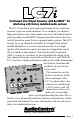
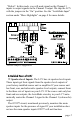
USER MANUAL
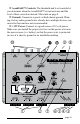

Remote In: In some installations, you may not want to use
the GTO™ to turn on your system. For these cases the LC7i can
be turned on remotely with a +12-volt trigger. When you use the
+12-volt remote in, you should set the internal GTO™ jumper (see
“Under the Hood” on page 6) to “Defeat”. This will prevent the
car’s network system from turning the system on unexpectedly.
Remote Out: Supplies 12 volts “+” when the LC7i is pow-
ered up, and is used to turn on external devices like signal proces-
sors and ampliers. Recommend fusing at 1 amp.
Maximized Indicator: This brightly colored LED indicates
when the signal level is just below clipping within your LC7i.
When properly level matched, this LED should icker occasionally
when your system is playing at its maximum volume level.
Power: If you have connected all of your power wires cor-
rectly, this light should be bright red when your system turns on.
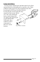
Optional (ACR-1) Dash Mounted Control Input: You can
add a dash control that allows you to set remotely the level of the
subwoofer.
Pre-Amp Outputs: These RCA plugs should be connected to
the next component after the LC7i, such as a crossover or ampli-
er. Do not connect any speakers directly to your LC7i outputs.
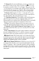
Output Levels: These knobs allow you to adjust the signal
level from your source unit to match the input of your after-market
ampliers. Ideally you want to keep the output of the LC7i high
and keep the amplier gain(s) as low as possible.
Channel Summed Indicators: Under the cover of your LC7i
are jumpers that will allow you to sum selected channels into the
main (#1) channels. This is especially useful for factory-installed
systems with actively crossed over speaker systems. These indica-
tor LED’s let you know which channels are being summed into the
main inputs.
page 7