
Installation guide
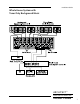


ARCHITECT
Model 1280 EQ • Model 1260
Model 1680 EQ • Model 1660
Installer’s Guide
™
Installation Guide
9
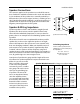
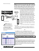
Speaker Connections
The same rule applies to the speaker wires as the RCA connec-
tions. Establish a standard connection color code and stick with
it. One conductor of the speaker wire is normally marked by a
dierent color (silver versus copper) or there is a ribbing on one
side. Typically this marked conductor is used for the positive (+)
speaker leads. Of course the really good wire has Positive and
Negative printed right onto the wire jacket.
Speaker & Wiring Impedance
Speaker impedance often is and should be straight forward.
Speakers, like other resistors, wired in parallel “show” lower
values than the individual components. In case you have for-
gotten, there is an example here for calculating speakers wired
in parallel.
Often the real world is more complicated than theory and for
speakers this is the case. An eight ohm speaker is not eight
ohms at all frequencies. Plus passive crossover networks add
their own changing conditions. What you should be aware of
and sensitive to are speakers that have signicant dips from
“nominal” values in portions of their frequency range and
speakers that are rated at unusual impedances, for example 3.5
ohms. The Architect is tolerant of lower impedance loads, how-
ever, all good designs use some margin of error.
Your choice of speaker wire gauge and the length of the runs
also aects the speaker impedance load presented to the am-
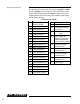
Speaker connection wiring
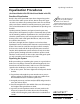
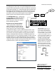
Speaker Wire Resistance Wire Gauge versus Run Length
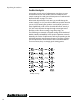
Calculating Impedance
For three 8 ohm speakers wired in
parallel (pluses connected to pluses)
the impedance is
1/8 + 1/8 + 1/8 = 3/8
Then take the inverse or
8/3 = 2.66 ohms
25’ 50’ 100’ 250’ 500’
24 GA 1.3 Ω 2.6 Ω 5.1 Ω 12.8 Ω 25.7 Ω
22 GA 0.8 Ω 1.6 Ω 3.24 Ω 8.1 Ω 16.0 Ω
20 GA 0.5 Ω 1.0 Ω 2.0 Ω 5.0 Ω 10.1 Ω
18 GA 0.3 Ω 0.6 Ω 1.28 Ω 3.2 Ω 6.4 Ω
16 GA 0.2 Ω .4 Ω 0.8 Ω 2.0 Ω 4.0 Ω
14 GA 0.1 Ω .25 Ω 0.5 Ω 1.26 Ω 2.5 Ω
12 GA 0.08 Ω .16 Ω 0.32 Ω 0.8 Ω 1.6 Ω
pliers. As you can see in this
table, even fairly short speak-
er runs can have signicant
resistance if you use a smaller
wire gauge. This can be a ben-
et if you are paralleling lots
of speakers. The wire itself
acts as an impedance limiter,
since the amplier cannot
see a speaker load lower than
the resistance of the wire. The
downside of this resistance
in the wire is that you waste
some part of the total power
available to the speakers.