
User Manual

Operation Manual
46
Master Section
© 8.21
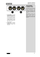
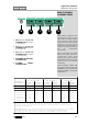
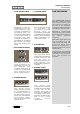
This panel contains the
connectors for the multi-
track tape recorder. Rather
than having individual
connectors for each group
output it is much more
convenient (and quicker to
make a connection) if they
are on multi-pole
connectors.
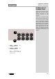
The multi-track recorder
sends are split across 3
connectors with each
carrying the group outputs
for 8 tracks. The sub-group
outputs are on a fourth
connector.
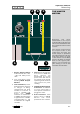
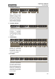
The multitrack sends and
sub group outputs are also
available (as a cost option)
on 56 pin EDAC multi-pole
connectors.
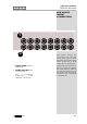
1 3245
1 MULTI-TRACK
CONNECTOR for tracks
1 through 8.
2 MULTI-TRACK
CONNECTOR for tracks
9 through 16.
3 MULTI-TRACK
CONNECTOR for tracks
17 through 24.
4 SUB-GROUP OUTPUT
CONNECTOR.
5 POWER INPUT
CONNECTOR.
MULTI-TRACK
CONNECTORS
MULTI-PIN CONNECTIONS
SIGNAL
NUMBER
+VE SIGNAL -VE SIGNAL SCREEN
D-SUB
PIN
EDAC
PIN
D-SUB
PIN
EDAC
PIN
D-SUB
PIN
EDAC
PIN
1/9/17 24
A
12
E
25
F
2/10/18 10
C
23
B
11
H
3/11/19 21
D
9
K
22
J
4/12/20 7
P
20
V
8
N
5/13/21 18
Z
6 d 19
U
6/14/22 4 c 17 f 5
Y
7/15/23 15 j 3 n 16 m
8/16/24 1 t 14 y 2 s
Note : All undesignated pins are unconnected. All screen
connections are joined inside the console and connected to
metalwork earth.
Patchbays: Tie lines connections 25-32 etc follow the same
wiring convention shown above. Consoles fitted with
patchbays do not have the option of EDAC connectors.