
Specifications
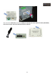


11
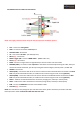
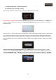
2.4. POWER connector cables and connections:
NOTE: The supply connection must always be the last step in the installation process.
• ACC – Connect to +12V Ignition
• GND – Connect to the vehicle’s Ground point
• GPIO-ZO: MMI – No function
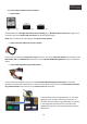
• IR – Connect the “IR cable” - (IR cable (4P)*1ea)
• PB12 (N.C) – No function
• MODE: Toggle S/W – Connect “MODE cable” - (MODE cable *1ea)
• OPT2 (N.C) – No function
• REAR – Connect to a signal from rear light bulb if you want to install a rear view camera
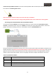
• PARKING (SAFE) – Connection cable “optional” to the vehicle’s hand break (Connecting this cable, when you
remove the vehicle hand break, you will stop seeing the interface images (“Security mode”) TV FREE OFF
• IR-NAVI – No function
• IR-AV1 (DVD) – Connection cable to the “IR control” cable from the multimedia device connected to the RCA
AV1 entry of the multimedia interface, to enable his own controls using the touch screen (optional)
• IR-AV2 (DMB) – Connection cable to the “IR control” cable of the multimedia device connected to the RCA
AV2 entry of the multimedia interface, to enable his own controls using the touch screen (optional)
• CAN H – Cable for the CAN H Infotainment connection (orange-green, Gateway or climate panel)
• CAN L – Cable for the CAN L Infotainment connection (orange-brown, Gateway o climate panel)
• RGB – Connect the RGB OUT connector of the GPS Box cables
• AUX-ON (N.C) – No function
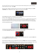
NOTE: The manufacturer may change the pins and colors here shown, please check every connection and cable
before proceed to install. Insulate the cables that won’t be used.