
Manual for 7-Day Programmable Thermostat (395KB)


54
1.5 CONNECT THE LABELLED WIRES TO THE THERMOSTAT
1. Connect the system wires to the thermostat terminals according to the wiring
diagram shown in section 1.6.
2. Make sure that the wires are pushed well back into the wall.
3. If you own a CT240 telephone controller, refer to section 6.1 for connection.
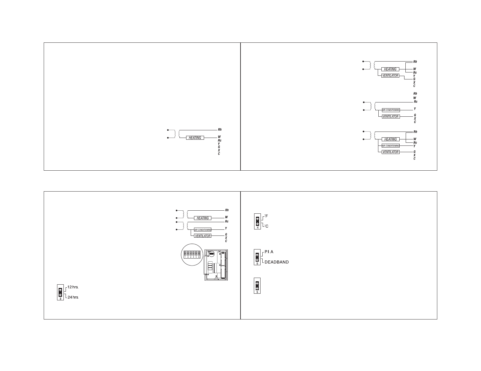
1.6 WIRING DIAGRAMS
The TH141 thermostat is compatible with most heating and air conditioning
systems. Multi-level heating and air conditioning systems, Milivolt control heating
systems, heat pumps and baseboard heating units are not compatible with this
thermostat. Baseboard units can be connected using a 24 V relay.
1.6.1 2-WIRE HEATING SYSTEM
1. Connect the heating relay to terminal W.
2. Connect the 24 V transformer to terminal Rh.
In this case, the order of connection is unimportant.
1.6.2 3-WIRE HEATING SYSTEM WITH FAN CONTROL
1. Connect the heating relay to terminal W.
2. Connect the fan relay to terminal G.
3. Connect the 24 V transformer to terminal Rh.
4. Connect a wire between terminals Rh and Rc.
1.6.3 3-WIRE AIR CONDITIONING SYSTEM WITH FAN CONTROL
1. Connect the air conditioning relay to terminal Y.
2. Connect the fan relay to terminal G.
3. Connect the 24 V transformer to terminal Rc.
1.6.4 4-WIRE HEATING AND AIR CONDITIONING SYSTEM
1. Connect the heating relay to terminal W.
2. Connect the air-conditioning relay to terminal Y.
3. Connect the fan relay to terminal G.
4. Connect the 24 V transformer to terminal Rh.
5. Connect a wire between terminals Rh and Rc.
76
b) Temperature in °C or °F
Default configuration of the TH141 is in °F. If you wish to change the
temperature to °C, push #4 switch down. Please note that if you
change from °F to °C, your comfort and economy settings will need to be
reconfigured as well.
c) Regulation Modes
Y
ou have a choice between two regulation modes:
1. Proportional adaptive mode
This mode analyses previous cycles in order to define the length of the up
coming cycle. This operating mode guarantees optimal regulation based on
the capacity of your system. To avoid cycles that are too short for the
heating or air-conditioning units, minimum On and Off duration is limited to
10% of the period (1.5 minutes for a 15 minute cycle).
1.6.5 5-WIRE HEATING AND AIR-CONDITIONING SYSTEM
1. Connect the heating relay to terminal W.
2. Connect the air-conditioning relay to terminal Y.
3. Connect the fan relay to terminal G.
4. Connect the 24 V transformer to terminal Rh.
5. Connect the 24 V air conditioning transformer to
terminal Rc.
1.7 THERMOSTAT CONFIGURATION
Before mounting the thermostat on the wall, configure it
using the switch bank on the back side of the unit.
a) 24 hrs. or 12 hrs. Display
The TH141 offers a 12 hrs. or 24 hrs. mode display. Default
configuration of the display is in the 12 hrs. mode. If you prefer a 24
hrs. display, push #3 switch down.
• Proportional adaptive
• Conventional with anticipation
If you want the proportional adaptive mode, push #5 switch up.