
Manual for 7-Day Programmable Thermostat (395KB)


1
b) To Erase a Program ................................17
c) Example 1 .......................................17
d) Example 2 .......................................18
3.2.2 Temporary or Permanent Temperature Bypass. . . ...............19
4. SELECT THE HEATING, AIR CONDITIONING, OR MIXED MODE...........20
5. FAN CONTROL ............................................21
6. TELEPHONE CONTROLLER ...................................21
6.1 Connection to the CT240 ...................................22
6.2 Connection to a House Automation System . . . . . . ...............22
6.3 Operating of the Telephone Interface . .........................23
7. BATTERY REPLACEMENT .....................................24
8. TECHNICAL SPECIFICATIONS ..................................25
WARRANTY .................................................26
1. INSTALLATION
1.1 REMOVE THE OLD THERMOSTAT
1 - Cut the power source to your heating or air conditioning system.
2 - Remove the cover of the old thermostat.
Caution: If, upon removing the wall plate, you see that it is mounted on a junction
box (similar to the junction box located behind an electrical switch or outlet), this
may indicate that it is a 120 V/240 V system. For more security, consult a qualified
electrician to check the installation.
1.2 INSTALL THE NEW THERMOSTAT
For a new installation, choose a location about 1.5 meters (5 feet) above the floor,
with good air circulation. The thermostat must be installed on an inside wall.
Avoid locations where there are:
a) air drafts (top of a staircase, air outlet,...)
b) dead air spots (behind a door,...)
c) direct sunlight
d) concealed chimneys or stove pipes.
32
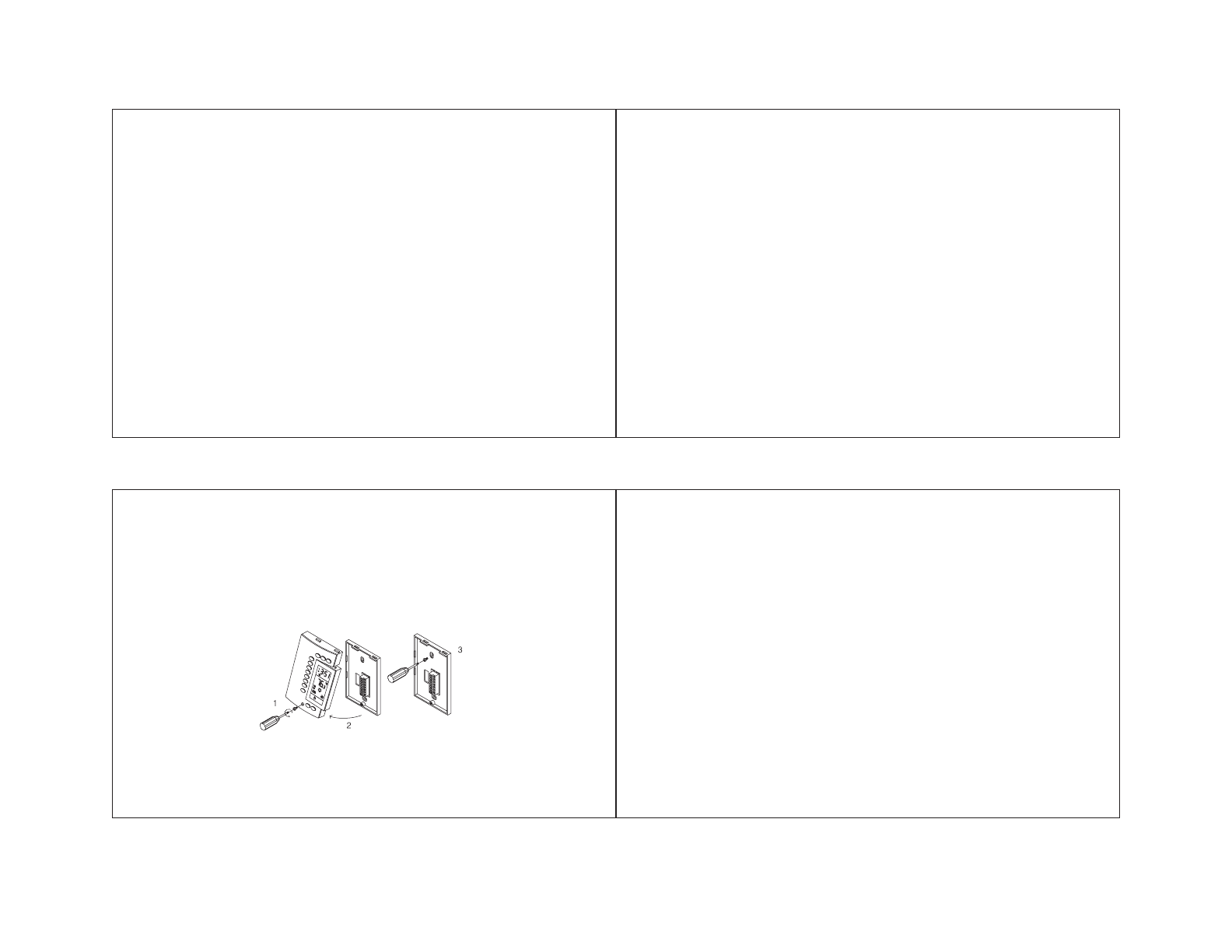
1.3 INSTALL AND CONNECT THE THERMOSTAT
1. Remove the screw holding the thermostat mounting plate.
2. Lift the lower part to separate the plate from the thermostat.
3. Mount the plate on the wall using the screws supplied.
1.4 IDENTIFY THE WIRES
1. If the wall plate of your old thermostat has more than two wires coming out of the
wall, you will need to label the wires. Start by identifying the letters close to each
screw or terminal on which a wire is connected. These terminals may be located
on either side of the plate.
2. Disconnect and identify each wire*.
3. You may need to tape the wires to the wall to keep them from falling back into it.
If the wall cavity is larger than necessary, fill it with insulating wool in order to
prevent the infiltration of warm or cold air behind the thermostat.
* If your installation is recent, the colour of the wires should match the identification on the
mounting plate.
(Rh) Red Heating power source
(W) White Heating relay
(Rc) Blue Air conditioning power supply
(Y) Yellow Air conditioning relay
(G) Green Fan relay