
Diamond Storage Array Installation, Operations, Maintenance Manual
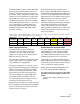
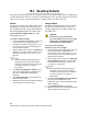
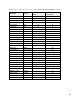
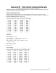
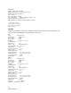
Table Of Contents
- Preface
- 1.0 Diamond Storage Array Product Overview
- 2.0 Diamond Storage Array Technical Overview
- 3.0 Installation Instructions
- 3.2 Physical Set Up
- 4.0 Determining Drive and Sled Designations
- 5.0 Accessing the Array
- Command Line Interface
- ATTO ExpressNAV
- In-band SCSI over Fibre Channel
- RS-232 port
- Ethernet port
- SNMP
- I/O details
- Browser compatibility
- Opening an ExpressNAV session
- Navigating ExpressNAV
- Exhibit 5.4-1 Atypical page in the ATTO ExpressNAV configuration tool.
- Status
- Ethernet
- SNMP
- Serial Port
- Fibre Channel
- Storage Management
- RAID
- Clear Data
- Logical Units
- Rebuild
- Configuration
- Advanced
- Restart
- Help
- FirmwareRestart
- Help
- RestoreConfiguration
- SaveConfiguration
- SystemSN
- VerboseMode
- EthernetSpeed
- FTPPassword
- IPAddress
- IPDHCP
- IPGateway
- IPSubnetMask
- SNMPTrapAddress
- SNMPTraps
- SNMPUpdates
- TelnetPassword
- TelnetTimeout
- TelnetUsername
- FcConnMode
- FcDataRate
- FcFairArb
- FcFrameLength
- FcFullDuplex
- FcHard
- FcHardAddress
- FcNodeName
- FcPortInfo
- FcPortList
- FcPortName
- FcWWName
- SerialPortBaudRate
- SerialPortEcho
- SerialPortHandshake
- SerialPortStopBits
- AudibleAlarm
- DiamondModel
- DiamondName
- DriveCopyStatus
- DriveInfo
- FcNodeName
- FcPortList
- FcPortName
- Help
- IdentifyDiamond
- Info
- LUNInfo
- SerialNumber
- SledFaultLED
- SMARTData
- Temperature
- VirtualDriveInfo
- FcScsiBusyStatus
- FirmwareRestart
- MaxEnclTempAlrm
- MinEnclTempAlrm
- Temperature
- Zmodem
- ATADiskState
- AutoRebuild
- ClearDiskReservedAreaData
- DriveCopy
- DriveCopyHalt
- DriveCopyResume
- DriveCopyStatus
- DriveInfo
- DriveSledPower
- DriveWipe
- IdeTransferRate
- LUNInfo
- LUNState
- QuickRAID0
- QuickRAID1
- QuickRAID5
- QuickRAID10
- RAID5ClearData
- RAID5ClearDataStatus
- RAIDInterleave
- RAIDHaltRebuild
- RAIDManualRebuild
- RAIDRebuildState
- RAIDRebuildStatus
- RAIDResumeRebuild
- RebuildPriority
- ResolveLUNConflicts
- RestoreModePages
- SledFaultLED
- VirtualDriveInfo
- 6.0 Configuring Drives
- JBOD (Just a Bunch of Disks)
- RAID Level 0
- RAID Level 1
- RAID Level 10
- RAID Level 5
- Interleave
- Hot Spare sleds
- Enhancing performance
- Sled-based versus disk-based
- Exhibit 6.2-1 Sled-based QuickRAID0 stripe groups with LUN designations in a fully populated Array set up as QuickRAID0 6 sled. If sled 6 were to be withdrawn from the array, LUN 3 (grayed boxes) would be unavailable.
- Exhibit 6.2-2 Drive-based QuickRAID0 stripe groups with LUN designations in a fully populated Array set up as QuickRAID0 6 Drive. If sled 6 were to be withdrawn from the array, LUNs 2 and 5 would be unavailable.
- Exhibit 6.2-3 Configurations of a fully populated Diamond Storage Array in RAID Level 0.
- Exhibit 6.3-1 Drive sleds, LUNs and mirror partners in a RAID Level 1 configuration.
- Hot Spare sleds
- Configuring a fully-populated array
- Configuring a partially-populated array
- Removing RAID groups
- Hot Spare sleds
- 7.0 Hardware Maintenance
- 8.0 Copying Drives
- 9.0 Updating Firmware
- 10.0 System Monitoring and Reporting
- RS-232 monitoring port and CLI
- Ethernet monitoring port and CLI
- Power On Self Test (POST)
- Ready LED
- Audible alarm
- Thermal monitoring
- Power supply monitoring
- System fault LED and error codes
- Disk drive activity and disk fault LEDs
- Windows 2000 special instructions
- Error messages
- Specific situations and suggestions
- Default
- Factory Default
- Appendix A ATA Disk Technology
- Appendix B Information Commands Results
- Appendix C Product Safety
- Appendix D Specifications
- Appendix E Warranty
81
ATTO Technology Inc. Diamond Storage Array Installation and Operation Manual
• a two second pause
• another series of blinks providing more detailed
information for technical personnel.
• a four-second pause
• the blink code sequence will repeat from step 1
until the error is cleared.
In general, any fault will require notification of
Diamond Array technical personnel for resolution
or for further debug instructions. When you report
an error code, please provide both the first and
second blink code values.
During a fault condition, more detailed
information about the fault may be available via
the CLI over the RS-232 interface port or the
optional Ethernet port. These error messages
should be reported to technical personnel to assist
in debugging the problem.
The blink codes are also saved internally by the
array to NVRAM (Non Volatile Random Access
Memory) and will be displayed at power up if the
power to the array is recycled.
Disk drive activity and disk fault LEDs
Each dual disk drive sled assembly contains two
green activity LEDs and an amber Disk Fault
LED. Once the system has successfully powered
up and passed POST, the green activity LEDs are
full on and the Disk Fault LED off.
The Drive 1 and Drive 2 activity LEDs will stay
full on when the system is operational and no disk
drive activity is present. As the disk drives are
accessed, the green LEDs will flash. If the disk
drives are heavily accessed the green activity
LEDs will appear to flash at a high rate or may
even appear to be completely turned off.
The amber Disk Fault LED will be off under
normal operation. If either of the disk drives on a
dual disk drive assembly reports a disk error of
any kind, the amber Disk Fault LED will come on.
The Disk Fault LED can be activated by minor
issues such as a disk drive writing to a bad sector
(which is usually corrected by the disk drive the
next time it writes) or major issues such as a head
crash or complete drive failure.
When the Disk Fault LED is turned on, the system
will issue a detailed message via the CLI. These
messages are not written permanently to the error
log file but should be recorded to help assess the
disk problem.
If the disk drive error is a non fatal error and the
drive is still functional, the array will continue to
read and write data to the disk drive but the Disk
Fault LED will remain on. If you repeat a drive
command or action and it completes successfully,
the Disk Fault LED may have been set by an
anomaly in the disk drive. You can clear the Disk
Fault LED by either power cycling the array or
issuing the SledFaultLED command in CLI as per
Diagnostic Commands
on page 41
If you repeat a disk command or action and the
Disk Fault LED remains on, the disk error may be
serious. You should write down the error message
issued by the CLI and contact technical support
via the means easiest for you for assistance (refer
to
Contact ATTO Technology, Inc.
on page viii). If you
choose to replace the suspected faulty dual disk
drive sled assembly, follow the appropriate
procedures.
Number of blinks Problem area
1, 2 or 3 processor or memory
4 Fibre Channel interface
5 SCSI interface
7 Fibre Channel connection
8 general internal processing
9 SCSI Enclosure Services