
Diamond Storage Array Installation, Operations, Maintenance Manual
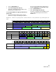
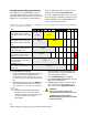
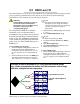
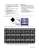

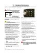
Table Of Contents
- Preface
- 1.0 Diamond Storage Array Product Overview
- 2.0 Diamond Storage Array Technical Overview
- 3.0 Installation Instructions
- 3.2 Physical Set Up
- 4.0 Determining Drive and Sled Designations
- 5.0 Accessing the Array
- Command Line Interface
- ATTO ExpressNAV
- In-band SCSI over Fibre Channel
- RS-232 port
- Ethernet port
- SNMP
- I/O details
- Browser compatibility
- Opening an ExpressNAV session
- Navigating ExpressNAV
- Exhibit 5.4-1 Atypical page in the ATTO ExpressNAV configuration tool.
- Status
- Ethernet
- SNMP
- Serial Port
- Fibre Channel
- Storage Management
- RAID
- Clear Data
- Logical Units
- Rebuild
- Configuration
- Advanced
- Restart
- Help
- FirmwareRestart
- Help
- RestoreConfiguration
- SaveConfiguration
- SystemSN
- VerboseMode
- EthernetSpeed
- FTPPassword
- IPAddress
- IPDHCP
- IPGateway
- IPSubnetMask
- SNMPTrapAddress
- SNMPTraps
- SNMPUpdates
- TelnetPassword
- TelnetTimeout
- TelnetUsername
- FcConnMode
- FcDataRate
- FcFairArb
- FcFrameLength
- FcFullDuplex
- FcHard
- FcHardAddress
- FcNodeName
- FcPortInfo
- FcPortList
- FcPortName
- FcWWName
- SerialPortBaudRate
- SerialPortEcho
- SerialPortHandshake
- SerialPortStopBits
- AudibleAlarm
- DiamondModel
- DiamondName
- DriveCopyStatus
- DriveInfo
- FcNodeName
- FcPortList
- FcPortName
- Help
- IdentifyDiamond
- Info
- LUNInfo
- SerialNumber
- SledFaultLED
- SMARTData
- Temperature
- VirtualDriveInfo
- FcScsiBusyStatus
- FirmwareRestart
- MaxEnclTempAlrm
- MinEnclTempAlrm
- Temperature
- Zmodem
- ATADiskState
- AutoRebuild
- ClearDiskReservedAreaData
- DriveCopy
- DriveCopyHalt
- DriveCopyResume
- DriveCopyStatus
- DriveInfo
- DriveSledPower
- DriveWipe
- IdeTransferRate
- LUNInfo
- LUNState
- QuickRAID0
- QuickRAID1
- QuickRAID5
- QuickRAID10
- RAID5ClearData
- RAID5ClearDataStatus
- RAIDInterleave
- RAIDHaltRebuild
- RAIDManualRebuild
- RAIDRebuildState
- RAIDRebuildStatus
- RAIDResumeRebuild
- RebuildPriority
- ResolveLUNConflicts
- RestoreModePages
- SledFaultLED
- VirtualDriveInfo
- 6.0 Configuring Drives
- JBOD (Just a Bunch of Disks)
- RAID Level 0
- RAID Level 1
- RAID Level 10
- RAID Level 5
- Interleave
- Hot Spare sleds
- Enhancing performance
- Sled-based versus disk-based
- Exhibit 6.2-1 Sled-based QuickRAID0 stripe groups with LUN designations in a fully populated Array set up as QuickRAID0 6 sled. If sled 6 were to be withdrawn from the array, LUN 3 (grayed boxes) would be unavailable.
- Exhibit 6.2-2 Drive-based QuickRAID0 stripe groups with LUN designations in a fully populated Array set up as QuickRAID0 6 Drive. If sled 6 were to be withdrawn from the array, LUNs 2 and 5 would be unavailable.
- Exhibit 6.2-3 Configurations of a fully populated Diamond Storage Array in RAID Level 0.
- Exhibit 6.3-1 Drive sleds, LUNs and mirror partners in a RAID Level 1 configuration.
- Hot Spare sleds
- Configuring a fully-populated array
- Configuring a partially-populated array
- Removing RAID groups
- Hot Spare sleds
- 7.0 Hardware Maintenance
- 8.0 Copying Drives
- 9.0 Updating Firmware
- 10.0 System Monitoring and Reporting
- RS-232 monitoring port and CLI
- Ethernet monitoring port and CLI
- Power On Self Test (POST)
- Ready LED
- Audible alarm
- Thermal monitoring
- Power supply monitoring
- System fault LED and error codes
- Disk drive activity and disk fault LEDs
- Windows 2000 special instructions
- Error messages
- Specific situations and suggestions
- Default
- Factory Default
- Appendix A ATA Disk Technology
- Appendix B Information Commands Results
- Appendix C Product Safety
- Appendix D Specifications
- Appendix E Warranty

69
ATTO Technology Inc. Diamond Storage Array Installation and Operation Manual
7.0 Hardware Maintenance
The disk drive sleds, blower assemblies, power supplies, host interface cards, and system management
card may be replaced with identical or upgraded parts.
WARNING
The only way to completely de-energize the unit is
to turn off both power
supplies and unplug both
power cords from the
back of the unit.
Turning the power switch
to the Stand-by position
on one power supply
does not completely turn
off power to the array; it is not an AC on-off switch.
Power may still be in the unit through the other
power supply.
CAUTIONCAUTION
All modular components must be replaced
by qualified personnel only.
Do not leave empty openings in the Diamond
Storage Array. Empty openings affect airflow and
may cause the unit to overheat and shut down.
Components are electrostatic sensitive. Use
proper grounding methods when working with or
around the array.
Always store spare components in proper ESD
containers when not in use.
The power supply and blower assembly may be
replaced while the unit is running. (Refer to
Hot Swap
Operating Instructions on page 71
)
• Host interface cards and management cards may only
be replaced when the Diamond Storage Array is off.
Backup the unit fully before replacing these
components.
• You may remove a disk drive sled while the array is
powered on. Refer to the instructions in
Hot Swap
Operating Instructions on page 71
for details.
To remove a management card
1 Power down both power supplies.
2 Loosen the screws holding the card in place.
3 Pull out the assembly and replace it with
another.
4 Securely tighten all screws after replacing the
component.
To remove a disk drive sled (Exhibit 7-2)
1 Loosen the screws on either side of the assembly
2 Pull on the assembly’s handle and carefully
slide it out of its bay.
3 Replace the disk drive sled with another sled.
To remove a Host Interface Card
1 Power down both power supplies
2 Remove any cable attached to the port.
3 Loosen the retaining screws
4 Pull the Host Interface Card out of the unit.
5 To replace the card, push it back into the unit
and tighten the retaining screws.
To remove the power supply (Exhibit 7-4),
1 Press the Stand-by power switch to the off position
2 Remove the power cord
3 Using a No. 1 Phillips screwdriver, loosen the
screws holding the assembly in place.
4 Pull out the assembly and replace it with
another.
5 Securely tighten all screws after replacing the
component.
To remove a blower assembly (Exhibit 7-4),
1 Using a No. 1 Phillips screwdriver, loosen the screws
holding the assembly in place.
2 Pull out the assembly and replace it with
another.
3 Securely tighten all screws after replacing the
component.
WARNING
Do not leave empty openings on the front
or rear of the Diamond Storage Array under
any circumstances.
Power Switch Positions
On Stand-by
E
xhibit
7
-1: The management card may be accessed via a
s
erial port DB-9 connector or an optional Ethernet
connection.