
Diamond Storage Array Installation, Operations, Maintenance Manual

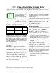
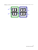
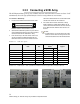

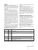
Table Of Contents
- Preface
- 1.0 Diamond Storage Array Product Overview
- 2.0 Diamond Storage Array Technical Overview
- 3.0 Installation Instructions
- 3.2 Physical Set Up
- 4.0 Determining Drive and Sled Designations
- 5.0 Accessing the Array
- Command Line Interface
- ATTO ExpressNAV
- In-band SCSI over Fibre Channel
- RS-232 port
- Ethernet port
- SNMP
- I/O details
- Browser compatibility
- Opening an ExpressNAV session
- Navigating ExpressNAV
- Exhibit 5.4-1 Atypical page in the ATTO ExpressNAV configuration tool.
- Status
- Ethernet
- SNMP
- Serial Port
- Fibre Channel
- Storage Management
- RAID
- Clear Data
- Logical Units
- Rebuild
- Configuration
- Advanced
- Restart
- Help
- FirmwareRestart
- Help
- RestoreConfiguration
- SaveConfiguration
- SystemSN
- VerboseMode
- EthernetSpeed
- FTPPassword
- IPAddress
- IPDHCP
- IPGateway
- IPSubnetMask
- SNMPTrapAddress
- SNMPTraps
- SNMPUpdates
- TelnetPassword
- TelnetTimeout
- TelnetUsername
- FcConnMode
- FcDataRate
- FcFairArb
- FcFrameLength
- FcFullDuplex
- FcHard
- FcHardAddress
- FcNodeName
- FcPortInfo
- FcPortList
- FcPortName
- FcWWName
- SerialPortBaudRate
- SerialPortEcho
- SerialPortHandshake
- SerialPortStopBits
- AudibleAlarm
- DiamondModel
- DiamondName
- DriveCopyStatus
- DriveInfo
- FcNodeName
- FcPortList
- FcPortName
- Help
- IdentifyDiamond
- Info
- LUNInfo
- SerialNumber
- SledFaultLED
- SMARTData
- Temperature
- VirtualDriveInfo
- FcScsiBusyStatus
- FirmwareRestart
- MaxEnclTempAlrm
- MinEnclTempAlrm
- Temperature
- Zmodem
- ATADiskState
- AutoRebuild
- ClearDiskReservedAreaData
- DriveCopy
- DriveCopyHalt
- DriveCopyResume
- DriveCopyStatus
- DriveInfo
- DriveSledPower
- DriveWipe
- IdeTransferRate
- LUNInfo
- LUNState
- QuickRAID0
- QuickRAID1
- QuickRAID5
- QuickRAID10
- RAID5ClearData
- RAID5ClearDataStatus
- RAIDInterleave
- RAIDHaltRebuild
- RAIDManualRebuild
- RAIDRebuildState
- RAIDRebuildStatus
- RAIDResumeRebuild
- RebuildPriority
- ResolveLUNConflicts
- RestoreModePages
- SledFaultLED
- VirtualDriveInfo
- 6.0 Configuring Drives
- JBOD (Just a Bunch of Disks)
- RAID Level 0
- RAID Level 1
- RAID Level 10
- RAID Level 5
- Interleave
- Hot Spare sleds
- Enhancing performance
- Sled-based versus disk-based
- Exhibit 6.2-1 Sled-based QuickRAID0 stripe groups with LUN designations in a fully populated Array set up as QuickRAID0 6 sled. If sled 6 were to be withdrawn from the array, LUN 3 (grayed boxes) would be unavailable.
- Exhibit 6.2-2 Drive-based QuickRAID0 stripe groups with LUN designations in a fully populated Array set up as QuickRAID0 6 Drive. If sled 6 were to be withdrawn from the array, LUNs 2 and 5 would be unavailable.
- Exhibit 6.2-3 Configurations of a fully populated Diamond Storage Array in RAID Level 0.
- Exhibit 6.3-1 Drive sleds, LUNs and mirror partners in a RAID Level 1 configuration.
- Hot Spare sleds
- Configuring a fully-populated array
- Configuring a partially-populated array
- Removing RAID groups
- Hot Spare sleds
- 7.0 Hardware Maintenance
- 8.0 Copying Drives
- 9.0 Updating Firmware
- 10.0 System Monitoring and Reporting
- RS-232 monitoring port and CLI
- Ethernet monitoring port and CLI
- Power On Self Test (POST)
- Ready LED
- Audible alarm
- Thermal monitoring
- Power supply monitoring
- System fault LED and error codes
- Disk drive activity and disk fault LEDs
- Windows 2000 special instructions
- Error messages
- Specific situations and suggestions
- Default
- Factory Default
- Appendix A ATA Disk Technology
- Appendix B Information Commands Results
- Appendix C Product Safety
- Appendix D Specifications
- Appendix E Warranty

13
ATTO Technology Inc. Diamond Storage Array Installation and Operation Manual
3.2.2 Connecting a SCSI Array
The SCSI Diamond Storage Array uses a VHDCI connector and SCSI cables to connect to a host. It will
automatically detect the type of Host Interface Card it is using without any intervention.
To connect a SCSI array
1 Insert a SCSI VHDCI connector into the Host
Interface Card in the back of the array.
2 Connect the cable from your host system to one
of the VHDCI connectors on the Host Interface
Card connector on the back of the array.
3 If the SCSI array is the last device on the bus,
you must attach a VHDCI terminator to one
connector of the SCSI Host Interface Card or
connect a cable between the second connector
and the next device on the SCSI bus.
4 The SCSI Host Interface Card has a rotary
binary-coded hex switch which allows you to
set the SCSI ID of the HIC. Be sure the selected
ID is different from all other SCSI devices on
the bus.
Note
If slower devices are connected on the same
SCSI bus as the Ultra 160 array, the bus will
communicate at the rate of the slowest device.
Exhibit 3.2-3 SCSI cable options.
Exhibit 3.2-4 SCSI interface cards: left without terminators attached; right with a terminator attached.
Bus speed, MB/sec.
max.
Bus width,
bits
Max. bus lengths,
meters
Max. device
support
Single-ended LVD
SCSI-1 5 8 6 - 8
Fast SCSI 10 8 6 - 8
Fast Wide SCSI 20 16 6 - 16
Wide Ultra SCSI 40 16 3 - 4
Wide Ultra SCSI 40 16 1.5 - 8
Wide Ultra 2 SCSI 80 16 - 12 16
Ultra 3 or Ultra160 SCSI 160 16 - 12 16