
Diamond Storage Array Installation, Operations, Maintenance Manual

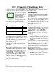
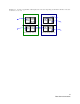
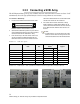

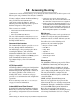
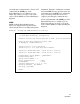
Table Of Contents
- Preface
- 1.0 Diamond Storage Array Product Overview
- 2.0 Diamond Storage Array Technical Overview
- 3.0 Installation Instructions
- 3.2 Physical Set Up
- 4.0 Determining Drive and Sled Designations
- 5.0 Accessing the Array
- Command Line Interface
- ATTO ExpressNAV
- In-band SCSI over Fibre Channel
- RS-232 port
- Ethernet port
- SNMP
- I/O details
- Browser compatibility
- Opening an ExpressNAV session
- Navigating ExpressNAV
- Exhibit 5.4-1 Atypical page in the ATTO ExpressNAV configuration tool.
- Status
- Ethernet
- SNMP
- Serial Port
- Fibre Channel
- Storage Management
- RAID
- Clear Data
- Logical Units
- Rebuild
- Configuration
- Advanced
- Restart
- Help
- FirmwareRestart
- Help
- RestoreConfiguration
- SaveConfiguration
- SystemSN
- VerboseMode
- EthernetSpeed
- FTPPassword
- IPAddress
- IPDHCP
- IPGateway
- IPSubnetMask
- SNMPTrapAddress
- SNMPTraps
- SNMPUpdates
- TelnetPassword
- TelnetTimeout
- TelnetUsername
- FcConnMode
- FcDataRate
- FcFairArb
- FcFrameLength
- FcFullDuplex
- FcHard
- FcHardAddress
- FcNodeName
- FcPortInfo
- FcPortList
- FcPortName
- FcWWName
- SerialPortBaudRate
- SerialPortEcho
- SerialPortHandshake
- SerialPortStopBits
- AudibleAlarm
- DiamondModel
- DiamondName
- DriveCopyStatus
- DriveInfo
- FcNodeName
- FcPortList
- FcPortName
- Help
- IdentifyDiamond
- Info
- LUNInfo
- SerialNumber
- SledFaultLED
- SMARTData
- Temperature
- VirtualDriveInfo
- FcScsiBusyStatus
- FirmwareRestart
- MaxEnclTempAlrm
- MinEnclTempAlrm
- Temperature
- Zmodem
- ATADiskState
- AutoRebuild
- ClearDiskReservedAreaData
- DriveCopy
- DriveCopyHalt
- DriveCopyResume
- DriveCopyStatus
- DriveInfo
- DriveSledPower
- DriveWipe
- IdeTransferRate
- LUNInfo
- LUNState
- QuickRAID0
- QuickRAID1
- QuickRAID5
- QuickRAID10
- RAID5ClearData
- RAID5ClearDataStatus
- RAIDInterleave
- RAIDHaltRebuild
- RAIDManualRebuild
- RAIDRebuildState
- RAIDRebuildStatus
- RAIDResumeRebuild
- RebuildPriority
- ResolveLUNConflicts
- RestoreModePages
- SledFaultLED
- VirtualDriveInfo
- 6.0 Configuring Drives
- JBOD (Just a Bunch of Disks)
- RAID Level 0
- RAID Level 1
- RAID Level 10
- RAID Level 5
- Interleave
- Hot Spare sleds
- Enhancing performance
- Sled-based versus disk-based
- Exhibit 6.2-1 Sled-based QuickRAID0 stripe groups with LUN designations in a fully populated Array set up as QuickRAID0 6 sled. If sled 6 were to be withdrawn from the array, LUN 3 (grayed boxes) would be unavailable.
- Exhibit 6.2-2 Drive-based QuickRAID0 stripe groups with LUN designations in a fully populated Array set up as QuickRAID0 6 Drive. If sled 6 were to be withdrawn from the array, LUNs 2 and 5 would be unavailable.
- Exhibit 6.2-3 Configurations of a fully populated Diamond Storage Array in RAID Level 0.
- Exhibit 6.3-1 Drive sleds, LUNs and mirror partners in a RAID Level 1 configuration.
- Hot Spare sleds
- Configuring a fully-populated array
- Configuring a partially-populated array
- Removing RAID groups
- Hot Spare sleds
- 7.0 Hardware Maintenance
- 8.0 Copying Drives
- 9.0 Updating Firmware
- 10.0 System Monitoring and Reporting
- RS-232 monitoring port and CLI
- Ethernet monitoring port and CLI
- Power On Self Test (POST)
- Ready LED
- Audible alarm
- Thermal monitoring
- Power supply monitoring
- System fault LED and error codes
- Disk drive activity and disk fault LEDs
- Windows 2000 special instructions
- Error messages
- Specific situations and suggestions
- Default
- Factory Default
- Appendix A ATA Disk Technology
- Appendix B Information Commands Results
- Appendix C Product Safety
- Appendix D Specifications
- Appendix E Warranty

10
Installation
General instructions
1 Insert the proper connector into the Host
Interface Card in the back of the array. (Refer to
Connecting a Fibre Channel Array
on page 11 for
Fibre Channel and
Connecting a SCSI Array
on
page 13 for SCSI).
2 Connect the cable (Fibre Channel or SCSI)
from your host system to the Host Interface
Card connector on the back of the array. The
cable you use depends upon your application,
the environment and distance.
3 Make sure the power switches on the power
supplies on the rear of the unit are in the stand-
by position. Plug in the power cords to the back
of the unit, then into an appropriate power
source (100-240 VAC). The power source must
be connected to a protective earth ground and
comply with local electrical codes. Improper
grounding may result in an electrical shock or
damage to the unit.
4 Press the stand-by power switch for each
power supply to the ON position. When the
green power LED on the back of the unit is lit,
the power supply is fully operational and
delivering power to the system. The power LED
on the front of the array will light once the
firmware begins to execute.
When the power is turned on, the LEDs on the
front of the array will flash twice. Drives will spin
up in groups of three, about every one to two
seconds. The individual LEDs will blink. After all
available drives have spun up, the individual
drive LEDs will stay lit. When all available
drives are operational, the ready LED on the
top front panel of the management card will
remain lit.
5 Reboot your computer
6 Determine the best configuration for your needs
(i.e. JBOD, RAID, etc.) and refer to the rest of
this manual for more detailed explanations and
configuration information.
Exhibit 3.2-1 Back side of a rack mount Fibre Channel Diamond Storage Array.