
Diamond Storage Array Installation, Operations, Maintenance Manual
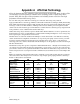
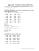
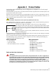


Table Of Contents
- Preface
- 1.0 Diamond Storage Array Product Overview
- 2.0 Diamond Storage Array Technical Overview
- 3.0 Installation Instructions
- 3.2 Physical Set Up
- 4.0 Determining Drive and Sled Designations
- 5.0 Accessing the Array
- Command Line Interface
- ATTO ExpressNAV
- In-band SCSI over Fibre Channel
- RS-232 port
- Ethernet port
- SNMP
- I/O details
- Browser compatibility
- Opening an ExpressNAV session
- Navigating ExpressNAV
- Exhibit 5.4-1 Atypical page in the ATTO ExpressNAV configuration tool.
- Status
- Ethernet
- SNMP
- Serial Port
- Fibre Channel
- Storage Management
- RAID
- Clear Data
- Logical Units
- Rebuild
- Configuration
- Advanced
- Restart
- Help
- FirmwareRestart
- Help
- RestoreConfiguration
- SaveConfiguration
- SystemSN
- VerboseMode
- EthernetSpeed
- FTPPassword
- IPAddress
- IPDHCP
- IPGateway
- IPSubnetMask
- SNMPTrapAddress
- SNMPTraps
- SNMPUpdates
- TelnetPassword
- TelnetTimeout
- TelnetUsername
- FcConnMode
- FcDataRate
- FcFairArb
- FcFrameLength
- FcFullDuplex
- FcHard
- FcHardAddress
- FcNodeName
- FcPortInfo
- FcPortList
- FcPortName
- FcWWName
- SerialPortBaudRate
- SerialPortEcho
- SerialPortHandshake
- SerialPortStopBits
- AudibleAlarm
- DiamondModel
- DiamondName
- DriveCopyStatus
- DriveInfo
- FcNodeName
- FcPortList
- FcPortName
- Help
- IdentifyDiamond
- Info
- LUNInfo
- SerialNumber
- SledFaultLED
- SMARTData
- Temperature
- VirtualDriveInfo
- FcScsiBusyStatus
- FirmwareRestart
- MaxEnclTempAlrm
- MinEnclTempAlrm
- Temperature
- Zmodem
- ATADiskState
- AutoRebuild
- ClearDiskReservedAreaData
- DriveCopy
- DriveCopyHalt
- DriveCopyResume
- DriveCopyStatus
- DriveInfo
- DriveSledPower
- DriveWipe
- IdeTransferRate
- LUNInfo
- LUNState
- QuickRAID0
- QuickRAID1
- QuickRAID5
- QuickRAID10
- RAID5ClearData
- RAID5ClearDataStatus
- RAIDInterleave
- RAIDHaltRebuild
- RAIDManualRebuild
- RAIDRebuildState
- RAIDRebuildStatus
- RAIDResumeRebuild
- RebuildPriority
- ResolveLUNConflicts
- RestoreModePages
- SledFaultLED
- VirtualDriveInfo
- 6.0 Configuring Drives
- JBOD (Just a Bunch of Disks)
- RAID Level 0
- RAID Level 1
- RAID Level 10
- RAID Level 5
- Interleave
- Hot Spare sleds
- Enhancing performance
- Sled-based versus disk-based
- Exhibit 6.2-1 Sled-based QuickRAID0 stripe groups with LUN designations in a fully populated Array set up as QuickRAID0 6 sled. If sled 6 were to be withdrawn from the array, LUN 3 (grayed boxes) would be unavailable.
- Exhibit 6.2-2 Drive-based QuickRAID0 stripe groups with LUN designations in a fully populated Array set up as QuickRAID0 6 Drive. If sled 6 were to be withdrawn from the array, LUNs 2 and 5 would be unavailable.
- Exhibit 6.2-3 Configurations of a fully populated Diamond Storage Array in RAID Level 0.
- Exhibit 6.3-1 Drive sleds, LUNs and mirror partners in a RAID Level 1 configuration.
- Hot Spare sleds
- Configuring a fully-populated array
- Configuring a partially-populated array
- Removing RAID groups
- Hot Spare sleds
- 7.0 Hardware Maintenance
- 8.0 Copying Drives
- 9.0 Updating Firmware
- 10.0 System Monitoring and Reporting
- RS-232 monitoring port and CLI
- Ethernet monitoring port and CLI
- Power On Self Test (POST)
- Ready LED
- Audible alarm
- Thermal monitoring
- Power supply monitoring
- System fault LED and error codes
- Disk drive activity and disk fault LEDs
- Windows 2000 special instructions
- Error messages
- Specific situations and suggestions
- Default
- Factory Default
- Appendix A ATA Disk Technology
- Appendix B Information Commands Results
- Appendix C Product Safety
- Appendix D Specifications
- Appendix E Warranty

vi
Diamond Storage Array Installation and Operation Manual
Appendix C Product Safety
Safe handling of the Diamond Storage Array will help protect its components as well as the people
working with them.
The Diamond Storage Array is heavy (92 pounds for the floor model, 86 pounds for the rack mount system). Two
people will be needed to move it safely.
Mechanical, shock and energy hazards are present through the system if one or more of the modules is removed.
There are no operator-serviceable components inside the unit except those indicated in
Hardware Maintenance
on
page 69 and
Hot Swap Operating Instructions on page 71
of this manual.
CAUTIONCAUTION
All modular components must be replaced by qualified personnel only.
This equipment must be connected to a protective earth ground in accordance with the instructions provided in
this guide. Improper grounding may result in an electrical shock.
When the power supply green LED is on, the power source is fully operational,
delivering power to the system. The only way to completely disconnect from the system
is to remove the AC power cord from the back of the unit from both power supply inputs.
The switch on the power supply is only a standby switch and does not disconnect the AC
from the system.
This unit is designed to only have inside communication lines connected to it (no lines
outside the building proper).
The Diamond Storage Array must be provided with adequate air flow. To reduce the risk of damage, the ambient
temperature of the inlet air should not exceed 40
o
C.
Service personnel must follow proper grounding methods when working with or around the system because of
the Diamond Storage Array’s electrostatic sensitive components. Use a static wriststrap when handling any
components from the Diamond Storage Array.
Safety compliances
• UL 1950 3rd Edition
• CSA 22.2 No. 950-95
• LEDs and fibre GBIC are Class 1 Laser Rated
EMC specifications
• EN 55022: class A
• ENV 50204 RF Immunity 900 MHz Pulse
• EN 6100-4-8 Magnetic Immunity
• EN 61000-4-2: ESD
• EN 61000-4-3: Radiated Immunity
• EN 61000-4-4: EFT
• EN 61000-4-5: Surge
• EN 61000-4-6: Conducted Immunity
• EN 61000-4-11: Voltage Dips and Interruptions
Radio and television interference
WARNING
This equipment has been tested and found to comply with the limits for a Class A digital device,
pursuant to Part 15 of the FCC rules. These limits are designed to provide reasonable protection
against harmful interference in a commercial environment. This equipment generates, uses and
can radiate radio frequency energy and, if not installed and used in accordance with the
instruction manual, may cause harmful interference to radio communications. Operation of this
equipment in a residential area is likely to cause harmful interference in which case the user will
be required to correct the interference at his own expense.
Power Switch Positions
On Stand-by