InBox / OutBox Wall mounted, PoE CobraNet® Endpoint User Manual For InBox X2, InBox R8, InBox M3, OutBox X2, and OutBox R8 Date 11/12/2010 Revision 04 Attero Tech, LLC 1315 Directors Row, Suite 107, Ft Wayne, IN 46808 Phone 260-496-9668 • Fax 260-496-9879 614-00005-04
InBox / OutBox User Manual IMPORTANT SAFETY INSTRUCTIONS The symbols below are internationally accepted symbols that warn of potential hazards with electrical products. This symbol, wherever it appears, alerts you to the presence of uninsulated dangerous voltage inside the enclosure -voltage that may be sufficient to constitute a risk of shock. This symbol, wherever it appears, alerts you to important operating and maintenance instructions in the accompanying literature. Please read the manual. 1. 2. 3. 4.
InBox / OutBox User Manual Note: This equipment has been tested and found to comply with the limits for a Class B digital device, pursuant to Part 15 of the FCC Rules and EN55022. These limits are designed to provide reasonable protection against harmful interference when the equipment is operated in a commercial environment.
InBox / OutBox User Manual Contents 1 – Overview ..............................................................................................................................................................................................................................1 2 – Installation..........................................................................................................................................................................................................................3 2.
InBox / OutBox User Manual APPENDIX C – Reference Documents .......................................................................................................................................................................
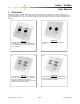
InBox / OutBox User Manual 1 – Overview The InBox and OutBox CobraNet audio interfaces provide a cost effective and efficient way to allow CobraNet audio connectivity directly at the wall. They provide inputs to or outputs from any CobraNet system and are compatible with any standard CobraNet device. There are five different modules in the family: InBox X2, OutBox X2, InBox R8, OutBox R8, and InBox M3.
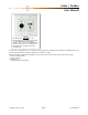
InBox / OutBox User Manual InBox M3 The InBox M3 has a single XLR or TRS balanced input with switchable mic/line gain, +12 V phantom power, and a clipping indicator. There are also two unbalanced line level RCA inputs and a 3.5 mm unbalanced stereo jack input. All inputs can be used simultaneously. All of the units are designed to fit in a standard dual gang junction box and feature 802.3af Power over Ethernet (PoE), so all connectivity for both power and audio is provided by a single CAT-5 cable.
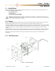
InBox / OutBox User Manual 2 – Installation All InBox and OutBox devices are installed in exactly the same manner. They require the same fittings and wiring. The items that are required for installation include: o InBox or OutBox product o Set of mounting screws o Decora face plate o Low voltage back box (not supplied) o Terminated Cat-5 cable (not supplied) Warning: Do not mount the InBox or OutBox in a fully enclosed junction box. The enclosed space can cause an undesirable temperature increase.
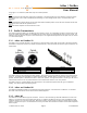
InBox / OutBox User Manual Using Figure 1 as a reference, follow these steps to install the product. Step 1 A cut out in the wall will need to be made prior to installation. The cutout needs to be large enough to securely fit an Old Work Bracket such as the Carlon SC200RR (drywall mounting) or a Low Voltage bracket such as a Carlon SC200A (stud mounting). Step 2 Connect the Ethernet cable to the RJ45 on the back of the InBox or OutBox product.
InBox / OutBox User Manual 2.4 – Audio Setup Audio setup of the InBox and OutBox can be done in various ways but all will involve setting up transmit and receive bundles by passing parameters to and from the device using SNMP1. Attero Tech provides the Control Center application for control and configuration of all InBox and OutBox products, as well as general SNMP control of compatible CobraNet devices. This application allows quick and easy setup of transmit and receive bundles and related parameters.
InBox / OutBox User Manual 3 – Bundle Blending All CobraNet devices have a finite number of receivable audio channels and a finite number of bundle receivers with which to receive them. Typical rack-mounted DSPs that support CobraNet use four receive bundles containing eight channels each for a total of 32 received audio channels available via CobraNet. In some devices, the number of receive bundles is configurable but in many, the bundle/channel combination is fixed.
InBox / OutBox User Manual 3.1 – Example Bundle Blend using the InBox X2 Figure 3 - Bundle Blending Connection Diagram Figure 4 - Bundle blending example using InBox X2 Figure 3 shows the physical network of part of an example system that uses several InBox X2 units. Figure 4 shows how the bundle blending is going to be configured. Unit D has been designated as the bundle blender unit so the first step is to setup bundles to pass audio from units A, B, and C to unit D.
InBox / OutBox User Manual Figure 6 – Example Bundle Blender Bundle Receiver Setup Figure 7 – Example Bundle Blender Bundle Transmitter Setup On the bundle blender InBox X2 (Unit D), set up three bundle receivers to receive the above bundles. For each bundle receiver, route the incoming two channels to a different receiver submap. One bundle should pass its audio to submaps 33 and 34, the second to submaps 35 and 36 and the third to submaps 37 and 38.
InBox / OutBox User Manual 4 – Software Installation and Setup The Attero Tech Control Center application should be used to examine and modify device configurations for the InBox and OutBox devices. This includes not only the standard CobraNet features such as audio routing but also the device specific controls of the signal processing blocks the VoiceBox uses. Refer to the Attero Tech Control Center User’s Guide for installation and setup instructions.
InBox / OutBox User Manual 4.2 – InBox Controls The following section describes the operation and controls available for the following devices o InBox X2 - V1.0.2.563 o InBox R8 - V1.0.2.581 o InBox M3 - V1.0.2.44 The audio path in an InBox is shown in Figure 8 with each input has its own unique set of controls. Figure 8 – InBox DSP Architecture The audio from the local input is fed through an EQ stage, a Compressor stage, a Gain stage, and finally, a delay stage.
InBox / OutBox User Manual 4.2.1 – Input EQ The input EQ section consists of a low cut, a low EQ, a mid sweep, a high EQ, and finally, a high cut. The low cut and high cut filters provide frequency cutoff adjustment from 20 Hz to 20 kHz. They also have a bypass option. If the bypass indicator is red, the cut filter will have no effect. The low EQ and high EQ have a set frequency of 400 Hz and 3 kHz respectively. Both have gain adjustment from -12 dB to +12 dB.
InBox / OutBox User Manual 4.3 – OutBox Controls The following section describes the operation and controls available for the following devices o OutBox X2 - V1.0.2.615 o OutBox R8 - V1.0.2.612 The audio path in an OutBox is shown in Figure 14 with, like the InBox, each input has its own unique set of controls. Figure 14 – InBox DSP Architecture CobraNet audio routed to an output is directed through the DSP blocks for that particular output and before being passed to the D/A convertors for output.
InBox / OutBox User Manual 4.3.1 – Output Limiter The output limiter is a fixed ratio limiter with the ratio set to 100:1. Each limiter has four controls per channel. o A bypass toggle control, o A threshold control which ranges from -100 dB to 0 dB, o An attack control which ranges from 1 ms to 1 s o A release control that ranges from 10 ms to 30 s. The bypass control is active if the indicator is showing red.
InBox / OutBox User Manual 4.4 – General Controls All of the InBox and OutBox devices have the same general controls. 4.4.1 – Store New Power-up Default Although the settings of the controls are applied immediately to the controlled device, the values are not permanent and will be lost if the device is powered down. In order to ensure that the changes are retained, they must be committed to nonvolatile memory.
InBox / OutBox User Manual If mono mixing is enabled between 2 channels, only the mixed audio is made available for network transmission. This means only one output submap is required per mono mix. Rather than leave a spare output, the audio from any higher numbered inputs is shuffled up to the next free output submap. For example on the InBox R8, with no mono mixing, inputs 1 and 2 are available on output submaps 1 and 2, while inputs 3 and 4 are available on output submaps 3 and 4 and so on.
InBox / OutBox User Manual 5 – Troubleshooting Listed below are some common problems and possible cures. No communication o Ensure Ethernet cable is plugged in correctly to unit. o Ensure Ethernet cable is correctly plugged into an Ethernet switch. o Ensure port used on the Ethernet switch is PoE enabled and the switch has the corresponding port enabled. o Check the Ethernet switch indicator lights show correct PoE and link status.
InBox / OutBox User Manual 6 – Mechanical layout All of the following drawings show the devices with the Decora front plate attached. 6.
InBox / OutBox User Manual 6.
InBox / OutBox User Manual 6.
InBox / OutBox User Manual 6.
InBox / OutBox User Manual This page is intentionally blank Attero Tech LLC 2010 Page 21 614-00005-04
InBox / OutBox User Manual 7 – ARCHITECTS & ENGINEERS SPECIFICATIONS 7.1 – InBox X2 The CobraNet interface unit shall provide two mic/line analog inputs on front panel with XLR and TRS connectors. A selectable gain of 0dB or +30dB, and +12V phantom power option shall be provided via front panel switches for each analog input channel. The internal analog to digital signal conversion shall be performed at 24-bit resolution with a sampling frequency of 48 kHz.
InBox / OutBox User Manual 7.2 – InBox R8 The CobraNet interface unit shall provide eight line level analog inputs on front panel with RCA connectors. The internal analog to digital signal conversion shall be performed at 24-bit resolution with a sampling frequency of 48 kHz. The CobraNet interface unit shall receive power over the Ethernet cable from an 802.3af PoE compliant network switch. The CobraNet interface shall be wall mounted in a standard dual gang junction box.
InBox / OutBox User Manual 7.3 – InBox M3 The CobraNet interface unit shall provide a mic/line analog input on front panel with XLR and TRS connectors. A selectable gain of 0dB or +30dB, and +12V phantom power option shall be provided via front panel switches. The interface will also provide two line level analog inputs on front panel with RCA connectors as well as two line level inputs on the front panel with a 3.5mm stereo jack connector.
InBox / OutBox User Manual 7.4 – OutBox X2 The CobraNet interface unit shall provide two balanced outputs on front panel with XLR connectors. The internal digital to analog signal conversion shall be performed at 24-bit resolution with a sampling frequency of 48 kHz. The CobraNet interface unit shall receive power over the Ethernet cable from an 802.3af compliant network switch. The CobraNet interface shall be wall mounted in a standard dual gang junction box.
InBox / OutBox User Manual 7.5 – OutBox R8 The CobraNet interface unit shall provide eight single-ended outputs on front panel with RCA connectors. The internal digital to analog signal conversion shall be performed at 24-bit resolution with a sampling frequency of 48 kHz. The CobraNet interface unit shall receive power over the Ethernet cable from an 802.3af PoE compliant network switch. The CobraNet interface shall be wall mounted in a standard dual gang junction box.
InBox / OutBox User Manual APPENDIX A – Introduction to CobraNet CobraNet is an audio networking technology for delivery and distribution of real-time, high quality, uncompressed digital audio using a standard Ethernet network. It is implemented using a combination of hardware, firmware, and the CobraNet protocol. Unlike other audio networking or distribution technologies, CobraNet is a true network and exists on standard Ethernet networks using standard Ethernet hardware.
InBox / OutBox User Manual The modes are as follows: o Unicast – Used for one-to-one connections. In this mode, only one receiver at a time can receive this bundle. Once a link is established from this transmitted bundle to a receiver, any future requests for that bundle from other potential receivers will fail. o Multicast – Used for one-to-many connections. This mode broadcasts its contents over the entire network. There is no restriction on the number of receivers.
InBox / OutBox User Manual APPENDIX B – Mapped Audio Output Channels All the InBox units have the capability to forward on network audio (the bundle blending feature). However, the actual channels available to be forwarded are determined by the device type and if any channels are configured as Mono mixes. The following sections, one for each InBox type, shows how the various local and network audio channels on a device are mapped to the transmit submaps for all possible mono mix combinations.
InBox / OutBox User Manual B1.
InBox / OutBox User Manual B2 – InBox M3 B3 – InBox X2 Unlike the InBox M3 and InBox R8, the InBox X2 does not have mono mix capability and so the mapping is permanently fixed as shown.
InBox / OutBox User Manual APPENDIX C – Reference Documents The following table lists the relevant reference documents. Document Title CobraNet Programmer’s Reference (Cirrus Logic) http://www.cobranet.info/en/support/cobranet/design/bundle_assignments.
InBox / OutBox User Manual Attero Tech LLC 2010 Page i 614-00005-04