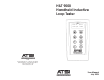
HILT 9000 Handheld Inductive Loop Tester R=12.3Ω Q=12.1 L=89.2µH 50KHz ATSI 8157 US Route 50 • Athens, OH 45701 (740) 592-2874 • Fax (740) 594-2875 sales@atsi-tester.com www.atsi-tester.
HILT 9000 - Inductive Loop Tester Table of Contents Receiving Your Shipment ......................................................... 2 Packaging ................................................................................ 2 Description ............................................................................. 3 Overview of HILT 9000 Controls .............................................. 5 Function Controls ................................................................... 5 Power ................
2 www.atsi-tester.com Warnings These safety warning are provided to ensure the safety of personnel and proper operation of the tester. • The tester must not be operated beyond its specified operating range. • Safety is the responsibility of the operator. Receiving your Shipment Upon receiving your shipment, be sure that the contents are consistent with the packing list. Notify your distributor or factory of any missing items.
HILT 9000 - Inductive Loop Tester General Description The HILT-9000 is designed to measure characteristics of an inductive loop at different frequencies; measure working parameters of the loop system; as well as simulate the detector by measuring the change of inductance. The measurement modes can be easily switched by pressing corresponding buttons on the keypad.
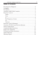
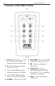
4 www.atsi-tester.com Overview of HILT 9000 Controls Ready: 100% Select Function Figure 1 1. LOOP: Measures RDC, L, and Q. If Q>15, use Q pushbutton to obtain actual value. 2. Q: Measures high Q values (when Q is >15). 3. Used in SET FREQ mode to increase frequency by 1KHz. 4. Used in SET FREQ mode to decrease frequency by 1KHz. 5. POWER: Turns unit On/Off. 6. SET FREQ: Selects operating frequency to measure L & Q. 7. ∆ L: Measures change of inductance. 8.
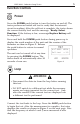
5 HILT 9000 - Inductive Loop Tester Function Controls Power Press the POWER push-button to turn the tester on and off. The tester performs an initial self-test to verify that the internal circuit is working. After the self-test is complete, the tester shows the current battery level and the message: Ready: Select Function. If the battery is low, a message Replace Battery will be displayed.
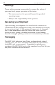
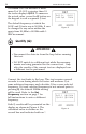
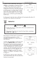
6 www.atsi-tester.com The LOOP test can measure a maximum Q of 15. If Q is greater than 15 the tester displays Q>15. To measure the actual value, press the Q button on the keypad to run a separate Q test. The default frequency at which the LOOP and Q tests run is 50 KHz. It can be changed to any value within the range from 20 KHz to 80 KHz with 1 KHz increment. R=12.3Ω L=89.2µH Q=12.1 50KHz Figure 3 Quality (Q) ATTENTION • Disconnect the detector from the loop before running this test.
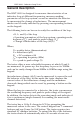
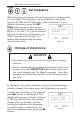
7 HILT 9000 - Inductive Loop Tester , , Set Frequency When the tester is powered, the test frequency is automatically set to 50 KHz. The frequency can be changed to any value between 20 KHz and 80 KHz with 1 KHz resolution. To set a different frequency press the SET FREQ push-button to view the freTest @ frequency quency adjustment display as show in F=50 KHz Figure 5. Use the ! or " push-button to increase or decrease the frequency by 1KHz.
8 www.atsi-tester.com If there is bad connection, the tester displays a message as shown in Figure 7. Make sure that the test leads are properly connected. If the leads are connected to the loop and the message is still present, it means that Q of the loop is too low to generate the oscillation or the inductance is out of range. This can be verified by performing the LOOP test.
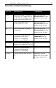
9 HILT 9000 - Inductive Loop Tester Function Controls Summary BUTTON DESCRIPTION COMMENTS LOOP Used to measure L, Q, and RDC of the loop. Q is measured up to 15.
10 www.atsi-tester.com Overview of Traffic Loop Detection Systems The inductive loop represents the most commonly used method to detect vehicles. The inductive loop is simply a coil of wires embedded into the pavement and can be characterized by several parameters, L (inductance), Q (quality factor), R (active resistance, measured using AC signal), and RDC (DC resistance).
HILT 9000 - Inductive Loop Tester 11 To guarantee a reliable oscillation in the loop system the quality factor (Q) of the loop with the lead-in wires should be above some value, determined by the amplifiers inside the detector. Deterioration of the loop and lead-in wires reduces Q and eventually prevents the system from oscillating even with a known good detector. Battery replacement NEVER OPEN THE BATTERY COMPARTMENT WHILE THE HILT -9000 POWER IS ON.
12 www.atsi-tester.com Commonly Asked Questions Q. Why do I have to disconnect the detector from the loop before running a Loop, Q, or ∆ L test? A. During Loop, Q, and ∆L test, the tester is applying its own signal to the loop. The tester verifies there is no signal on the loop before running these tests. However, with a scanning detector connected to the loop, there are time intervals during which the loop does not have a signal applied.
HILT 9000 - Inductive Loop Tester 13 Repair and Calibration To ensure that your instrument meets factory specifications, we recommend that it be returned to our factory at one-year intervals for calibration service. In addition to calibration of the test parameters, this service includes replacement of batteries and firmware updates. Please contact the factory for price and scheduling information on this service.
14 www.atsi-tester.com Technical and Sales Assistance If you are experiencing any technical problems, or require any assistance with the proper operation or application of your tester, please call, fax, or e-mail our technical support staff: ATSI 8157 US Route 50 • Athens, OH 45701 (740) 592-2984 (740) 594-2875 - Fax service@atsi-tester.
HILT 9000 - Inductive Loop Tester -- This page left blank -- 15
16 www.atsi-tester.com Limited Warranty The HILT 9000 (“Product”), distributed by Athens Technical Specialists, Inc. (ATSI), is warranted to the original purchaser (“Purchaser”) to be free of defects in materials and workmanship for a period of one year from the purchase date stated on the invoice. Within this period, in the event of a defect, malfunction, or other failure of the product while in the custody of the purchaser, ATSI will remedy the defect or cause of failure without charge to the Purchaser.