
User's Manual

Confidential Document
Page 9 of 28
3
3
.
.
4
4
.
.
D
D
B
B
9
9
C
C
o
o
n
n
n
n
e
e
c
c
t
t
o
o
r
r
W
W
i
i
r
r
i
i
n
n
g
g
D
D
i
i
a
a
g
g
r
r
a
a
m
m
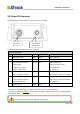
For connecting the device to PC when configuration is needed, the following diagram shows how to
solder/connect the DB9 connector.
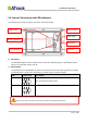
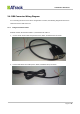
3.4.1. Using ATrack Serial Cable
Material needed: ATrack Serial Cable x 1, AS3 Power I/O cable x 1
1. Cut the ATrack Serial Cable and peel the Green, White, and Black wires as shown:
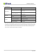
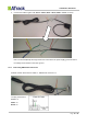
2. Peel the AS3 Power I/O Cable (Green, White, and Black wires) as shown: