
User's Manual

Confidential Document
Page 7 of 28
3
3
.
.
3
3
.
.
I
I
n
n
t
t
e
e
r
r
n
n
a
a
l
l
C
C
o
o
n
n
n
n
e
e
c
c
t
t
o
o
r
r
s
s
a
a
n
n
d
d
L
L
E
E
D
D
i
i
n
n
d
d
i
i
c
c
a
a
t
t
o
o
r
r
s
s
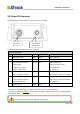
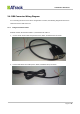
The following figure shows the internal connectors and its functionality.
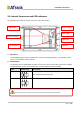
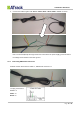
SIM Socket:
The AS3/AS3E supports a SIM card with either of these two operating voltages: 1.8V (ISO/IEC 7816-3
class C) or 3V (ISO/IEC 7816-3 class B).
RS232 Switch:
The pin#3(Green) and pin#5(White) of power I/O connector can be used for either general I/O or RS232.
The RS232 switch is used for the configuration. See table below for detail description:
Mode
Switch setup
Description
RS232 Mode
Pin#3(Green) and Pin#5(White) are acting as RS232 Tx and Rx.
This is manufactory default mode.
I/O Mode
Pin#3(Green) and Pin#5(White) are acting as general I/Os.
SIM Socket
RS232 Switch
PWR LED
GPS LED
3G LED
Battery connector
I/O Connector
Power off the device and make sure the wire connection before adjust RS232 switch.