
User's Manual

Confidential Document
Page 6 of 28
3
3
.
.
2
2
.
.
P
P
o
o
w
w
e
e
r
r
I
I
/
/
O
O
C
C
o
o
n
n
n
n
e
e
c
c
t
t
o
o
r
r
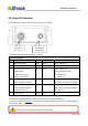
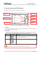
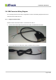
The following figure shows power I/O connector and its pin number.
The following table describes the function of each pin.
Power I/O Connector
Pin#
Function
Color
Designation
Note
1
Main power input
Red
PWR
DC 9V~40V input
2
ACC Input
Yellow
ACC
Ignition status positive trigger input
3**
General Input2 (Default)
Analog Input1
1-Wire Protocol Input *
RS232 Transmit data
Green
IO1
Positive trigger input
Analog input (DC0V~40V)
1-Wire Data input
See Chapter 5.1
4**
General Input1
General Output1 (Default)
Blue
IO2
Negative trigger input
Open collector output (Max.300mA)
5**
General Input3
General Output2 (Default)
RS232 Receive data
White
IO3
Negative trigger input
Open collector output (Max.300mA)
See Chapter 5.1
6
Power ground
Black
GND
*
The 1-Wire® Protocol supports up to three 1-Wire™ devices simultaneously, which means you can have
one (iButton® , DS1990A) and two 1-Wire™ temperature sensor probes (DS18B20).
** You may configure the AT$IOCG command to change these specific I/O pins to any of those functions
mentioned as above.
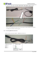
Power I/O
GPS Antenna
(AS3E Only)
Please do not connect a positive voltage to any output pin!