
User's Manual


Confidential Document
© ATrack Technology Inc. All Rights Reserved. Page 5 of 16
2
2
.
.
3
3
.
.
P
P
o
o
w
w
e
e
r
r
I
I
/
/
O
O
C
C
o
o
n
n
n
n
e
e
c
c
t
t
o
o
r
r
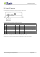
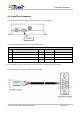
The following figure shows power I/O connector and its pin number of AK1
The following table shows its function of power I/O connector
Power I/O Connector
Pin#
Function Color Designation Note
1 Main power input Red PWR DC 9V~40V input
2 Power ground Black GND
3 ACC Input Yellow ACC Ignition status positive trigger input
4 General Input1 Green IN1 Negative trigger input
5 General Output1 Brown O1 Open collector output (Max.300mA)
6 General Output2 Gray O2 Open collector output (Max.300mA)
Positive Inputs: ACC (Triggered when connects to V+ range from 3.7 ~ 40V)
Negative Inputs: IN1 (Triggered when connects to ground range from 0.8 ~ 0V)
All outputs are open collector type (grounded when enabled) with max. sink current of 300mA.
Power I/O