SE8502-M12 Series IP68 Rated 2-Port Serial Server User’s Manual Version 1.1 Updated on December 31, 2010 TEL: 886-3-5508137 FAX: 886-3-5508131 http://www.atop.com.
User manual Version 1.1 SE8502-M12 IP68 Serial Server Important Announcement The information contained in this document is the property of Atop Technologies, Inc. and is supplied for the sole purpose of operation and maintenance of products of Atop Technologies, Inc.
User manual Version 1.1 SE8502-M12 IP68 Serial Server Contents 1.1. OVERVIEW ......................................................................................................................................................1 1.2. FEATURES........................................................................................................................................................1 1.3. PACKAGE CHECKLIST .......................................................................................
User manual Version 1.1 SE8502-M12 IP68 Serial Server 4.3. COM PORT CONFIGURATION ........................................................................................................................26 4.3.1. TCP Server Mode for Link Mode ...........................................................................................27 4.3.2. TCP Client for Link Mode.......................................................................................................28 4.3.3. UDP for Link Mode ......
User manual Version 1.1 SE8502-M12 IP68 Serial Server Introduction 1. 1.1. Overview SE8502-M12 is an Industrial 2-Port IP68 Serial Server, built for the uses of waterproof, dustproof, and vibrationresistant. There is a strong demand for reliable and rugged networking solutions, that can be used for the industrial workplace where is in harsh environmental conditions, such as high levels of moisture, dust, heat, electrical interference, and vibration.
User manual Version 1.1 SE8502-M12 IP68 Serial Server 1.3. Package Checklist Your SE8502-M12 is shipped with the following items. If any of these items is missing or damaged, please contact your customer service representative for assistance. SE8502-M12 Quick Start Guide. Product CD with user’s manual and configuration utility “ SerialManager” NOTE: Notify your sales representative if any of the above items is missing or damaged. 1.4.
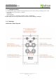
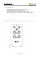
User manual Version 1.1 SE8502-M12 IP68 Serial Server 1.5. Panel/Wall Mounting To mount the SE8502-M12on the panel or wall, please follow up the steps below, 1. Select three proper screws and make holes on the panel or wall. 2. Insert the first screw into the top screw hole and screw it into panel or wall firmly. 3. Insert the another two screws into the two bottom holes and screw them into panel or wall firmly. .
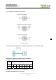
User manual Version 1.1 SE8502-M12 IP68 Serial Server 1.7 Pin assignment of LAN/ Serial / Power port NC = Not Assigned There are two wiring diagrams for straight-through and cross-over Ethernet cables. RJ45(8-pin) to RJ45(8-pin) straight-through cable wiring 10/100BaseT(X) Ethernet Port Connection RJ-45 Pin 1 2 3 Signal Tx+ Tx- Rx+ 4 5 6 7 8 Rx- RJ45(8-pin) to RJ45(8-pin) cross-over cable wiring 10/100BaseT(X) Ethernet Port Connection Copyright © 2010 Atop Technologies, Inc.
User manual Version 1.1 SE8502-M12 IP68 Serial Server RJ-45 2. Pin 1 2 3 4 Signal Rx+ Rx- Tx+ 5 6 7 8 Tx- Software Setup Now the SE8502-M12 hardware is installed and power is on, network IP configuration will be set in this section. 2.1. Default Settings The SE8502-M12 has an IP addresses one for Ethernet interface. These default settings are shown from under information Default IP addresses Interface Device IP Subnet mask Gateway IP LAN port 10.0.0.50.100 255.255.0.0 10.0.0.
User manual Version 1.1 SE8502-M12 IP68 Serial Server 2.1.1. Configure IP by SerialManager Utility Use SerialManager configuration utility that comes with product CD or diskette to configure the network parameters. For more details, please refer to Appendix B1. Find new device and IP assignment Use SerialManager Utility for finding new device IP address, get device’s current IP from table list Re-assigned IP, network mask and gateway if need with SerialManager Utility.
User manual Version 1.1 SE8502-M12 IP68 Serial Server Note: ARP commands can only be used to set a static IP address of SE8502-M12 - arp –a commands show the current mapping IP and MAC addresses. - arp –s “IP address” “MAC address” mapping the IP address to specify MAC address. 2.1.2. Configure IP by web interface Use common Web browser, ex. Microsoft Internet Explorer or Mozilla Firefox, to configure the network parameters of SE8502-M12. Open web browser, type in the IP address (default IP: 10.0.
User manual Version 1.1 SE8502-M12 IP68 Serial Server 2.3. TCP & UDP Protocols SE8502-M12 can be operated in two most common protocols TCP and UDP. 2.3.1. Transmission Control Protocol (TCP) TCP provides a connection and a byte oriented data stream with control parameters such as flow control, multiple ports option, and order delivery notification. Once the connection is established, data can be transmitted in both directions.
User manual Version 1.1 SE8502-M12 IP68 Serial Server Fig 5. TCP Connection in Virtual COM Mode TCP Server in Virtual COM Mode SE8502-M12 can be configured in the TCP server mode (PC as a client) with a unique IP and Port number, and SE8502-M12 waits passively for the PC to establish a connection to. After the connection is established, PC can communicate to serial devices through SE8502-M12.
User manual Version 1.1 SE8502-M12 IP68 Serial Server Fig 7. TCP Client in Virtual COM Mode 2.4.2. Tunneling Mode Tunneling Mode is used for multiple serial devices to “talk” among one another through SE8502-M12’s through wireless LAN or wired Ethernet. This mode is particularly useful when two or more serial devices are far away. This mode can be used to extend the normal serial communication distance of 15 m to 100 m or longer.
User manual Version 1.1 SE8502-M12 IP68 Serial Server UDP In UDP mode, User may exchange Multicast data from one SE8502-M12 with multiple SE8502-M12s, Vice versa is also true. Fig 10. UDP Link in Tunneling mode Configure SE8502-M12 in UDP Mode Use one of the three configuration methods (Telnet, Web, and console). User can configure SE8502-M12 to UDP mode. In UDP mode, SE8502-M12 can be configured to communicate to more than one node (Multicasting).
User manual Version 1.1 SE8502-M12 IP68 Serial Server Fig 12. Authorization request for system security The overview screen shall appear (Fig. 13) . 3.2. General Information This system overview window gives the general information on SE8502-M12, included Network, and Serial information. Fig 13. Overview for system information by Web Interface Device Information SE8502-M12’s system information includes Kernel version and AP version.
User manual Version 1.1 SE8502-M12 IP68 Serial Server Fig 14. Device Information from Overview web page Networking information Networking information fields are displayed both ‘LAN & MAC Address information. The information provided LAN MAC address. Fig 15. Network Information from Overview web page Serial Information SE8502-M12 COM1 (COM2) information includes UART mode, link mode, baud rate, parity, data bits, stop bits, flow control and link status.
User manual Version 1.1 SE8502-M12 IP68 Serial Server Fig 17. Network information by Web page Copyright © 2010 Atop Technologies, Inc.
User manual Version 1.1 SE8502-M12 IP68 Serial Server 3.3.1. LAN Settings Operation: [Network] Æ [LAN Setting] Click on the “Network” link and the following screen shall appear. Fill in IP information on TCP/IP field. Alternatively, click on DHCP to automatically obtain IP address, gateway and subnet mask information. Fig 18. LAN Setting from Network web page 3.3.2. DNS Settings Operation: [Network] Æ [DNS Settings] Click on the “Network” link and the following screen shall appear.
User manual Version 1.1 SE8502-M12 IP68 Serial Server Fig 20. SNMP Setting from Network web page 3.4. COM Port Configuration Here User can configure Serial parameters, include alias, baud rate, parity, data bit and type of flow control defined by user. Fig 21. COM port Information Web Page 3.4.1. Link Mode Settings Click on the “Serial” link and the Fig. 27 screen will appear.
User manual Version 1.1 SE8502-M12 IP68 Serial Server 3.4.2. TCP Server Mode TCP Server mode is default Link mode of Serial Settings, and it can wait for connecting requirement from remote host PC which running “serial-to IP” utility or setting SE8502-M12s in tunneling mode. User has to configure listening port to allow client establish connection to this server. Default port number of SE8502-M12 is 4660. IP filtering function is a simple ACL (Access Control List).
User manual Version 1.1 SE8502-M12 IP68 Serial Server Fig 23. TCP Client in Link mode 3.4.4. UDP Mode SE8502-M12 can be configured in a UDP mode to establish connection using Unicast or Multicast data from the serial device to one or multiple host computers. Vice versa is also true. For example, the original RS-422/ RS485 bus can be transferred and extended connected distance by SE8502-M12s. The destination IP is assigned by single IP or group IPs, The configuration is limited by the Local Listening Port.
User manual Version 1.1 SE8502-M12 IP68 Serial Server Configure UART Mode: RS-232 or RS-485 or RS-422 Baud rate: 110/150/300/600/1200/2400/4800/9600/19200/38400/57600/115200/230400/460800/921600 Parity: None or Odd or Even or Mark or Space Data bits: 5, 6, 7, 8 bits Stop bits: 1 or 2 Flow control: None or Xon/Xoff or Hardware (RTS/CTS). Fig 25. Serial Communication Settings from Web Page 3.4.6.
User manual Version 1.1 SE8502-M12 IP68 Serial Server 3.5.1. Configure Time by NTP Service Operation: SystemÆTime User can set date and time manually by fill in “Set Date and Time manually” field. User can also configure NTP Server to obtain Network time automatically. Fig 27. Time service settings from System web page 3.5.2. Security (change the Password) Operation: System->Security Click on the “Security” link and the following screen shall appear (Fig. 28).
User manual Version 1.1 SE8502-M12 IP68 Serial Server Fig 28. Change password from System Security Page Note: User may press the default reset key to reset password to the default value(blank) 3.5.3. Restoring Factory Default Configurations Operation: SystemÆ Set to Default User can click on “set to default and restart” button to restore SE8502-M12’s settings to factory default (Fig. 29). Fig 29. Set all parameters to factory default by Web Interface 3.5.4.
User manual Version 1.1 SE8502-M12 IP68 Serial Server 4. Telnet Configuration User can also use Telnet utility to change SE8502-M12 configuration settings. Open Ms-DOS command prompt window or other telnet tools Enter the “IP address” of the SE8502-M12 (For example, Telnet 10.0.50.100). The system then prompts for username and password, the default username is “admin” and the default password is null (blank). Fig 31. Login into System by Telnet Then the following main menu shall appear Fig 32.
User manual Version 1.1 SE8502-M12 IP68 Serial Server 4.1. General Information Operation: [Main]Æ[1 Overview] Select “1” from “Input choice (0~6) and enter:” to enter “overview page. This system overview window gives the general information on LAN IP, MAC address, SNMP information, kernel and AP version, and the connection status of the SE8502-M12 (Fig. 39). The following overview information shall appear.
User manual Version 1.1 SE8502-M12 IP68 Serial Server Serial Information: UART mode RS485/RS232/RS422 Link Mode: TCP Server [or TCP Client/UDP Mode, Allows for changes in Serial Page] Baud rate: 110/150/300/600/1200/2400/4800/9600/19200/38400/57600/115200/230400/460800/921600 Parity: None [or Even/Odd/Space/Mark...Allows for changes in Serial Page] Data bits: 5, 6, 7, 8 bits Stop bits 1 bit or 2 bits Flow Control None, Xon/Xoff, RTS/CTS 4.2.
User manual Version 1.1 SE8502-M12 IP68 Serial Server 4.2.1. LAN Settings Operation: [Main]Æ[2 Networking]Æ[1 LAN Settings] Select “1” from “Input choice (0~3) and enter on Networking page:” to enter LAN Settings page. The MAC address, IP address, subnet mask, gateway address, and IP mode information will be shown (Fig. 42). User also can set IP, Netmask, Gateway, and IP mode of LAN interfaces by enter the corresponding menus and values. For example, enter 1 for setting the IP address on LAN interface.
User manual Version 1.1 SE8502-M12 IP68 Serial Server 4.2.3. SNMP Settings Operation: [Main]Æ[2 Networking]Æ[3 SNMP Settings] Select “3” from “Input choice (0~3) and enter on Networking page:” to enter SNMP Settings page. User can enable/disable SNMP, and set network identification information on SNMP Settings page.
User manual Version 1.1 SE8502-M12 IP68 Serial Server Fig 38. Select COM Port from Serial Settings by Telnet Fig 39. The COM1 Setting page 4.3.1. TCP Server Mode for Link Mode Operation: [Main] Æ [4 Serial Settings] Æ [1 Link mode] Æ [1 TCP Server] TCP Server mode is default setting for Link mode of serial settings of SE8502-M12, and it can be configured to wait for the host computers to establish a connection with the serial device through SE8502-M12.
User manual Version 1.1 SE8502-M12 IP68 Serial Server Fig 40. TCP Server mode in link mode Note: Enable Virtual COM mode if the remote site PC’s “Serial to IP” tool is installed. 4.3.2. TCP Client for Link Mode Operation: [Main] Æ [4 Serial Settings] Æ [1 Link mode] Æ [2 TCP Client] User can configure SE8502-M12 to work in TCP Client mode.
User manual Version 1.1 SE8502-M12 IP68 Serial Server Operation: [Main] Æ [4 Serial Settings] Æ [1 Link mode] Æ [3 UDP] SE8502-M12 can be configured to work in UDP mode to establish connection using Unicast or Multicast protocol. Data can be transmitted from one or multiple serial devices to/from one or multiple host PCs and vice versa.
User manual Version 1.1 SE8502-M12 IP68 Serial Server Fig 43. Serial Settings by Telnet Note: The photo-couple isolation one, SE8502-M12, only supported max 230Kbps baud rate. 4.3.5. Packet Delimiter [Main] Æ [4 Serial Settings] Æ [8 Delimiter (Network to Serial)]/ [9 Delimiter (Serial to Network)] Packet delimiter is a way of controlling the number of packets in a serial communication. It is designed to keep packets in track.
User manual Version 1.1 SE8502-M12 IP68 Serial Server Fig 44. Configure Network Delimiter using Timer Configure Network Delimiter using Characters [Main]Æ[4 Serial Settings]Æ [8 Delimiter (Network to Serial)]/ [9 Delimiter (Serial to Network)] Æ[2 Characters] User can choose packet delimiter character pattern as the packet delimiter indicated in the Fig. 45 below: Fig 45. Configure Network Delimiter using Characters 4.4.
User manual Version 1.1 SE8502-M12 IP68 Serial Server Fig 46. Security settings by Telnet 4.4.1. Change the Password Operation: [Main] Æ [5 Security]Æ [1 Change Password] Enter desired password on “New password” fields. Fig 47. Changing the Password by Telnet Note: User may press the reset key on the product to reset to default password (blank). Copyright © 2010 Atop Technologies, Inc.
User manual Version 1.1 SE8502-M12 IP68 Serial Server APPENDIX A. USING VIRTUAL COM Virtual COM driver mode for windows converts COM port data (RS232) to IP data to control the RS-232C port on a SE8502-M12 over the IP network. By creating Virtual COM ports on the PC, Virtual COM redirects the communications from the Virtual COM ports to an IP address and port number on a SE8502-M12 which connected to the serial devices. The following figure is Virtual COM connection diagram. Fig 48.
User manual Version 1.1 SE8502-M12 IP68 Serial Server A.3 Virtual COM Communication Enable Virtual COM on SE8502-M12 by web interface From web browser access to SE8502-M12 by typing its IP address, click on “Serial” link to access Serial page, on the top half of the page click on “TCP Server” and enable Virtual COM by putting a check in front of the “Enable” checkbox, then type in the local port number in the “Local Port” field as indicated in the following screen. Fig 49.
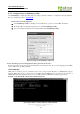
User manual Version 1.1 SE8502-M12 IP68 Serial Server Fig 51. Enable Virtual COM mode by Telnet Running Serial to IP for program on PC On Window Start Menu, go to\program\Serial/IP\Control panel\, The “Serial to IP for Control Panel” window shall appear. Then select the serial port. Fig 52. Detail setting from Serial/IP On the right of the panel is a sample for COM 4 settings. On the left is the list of the COM ports that have been selected (on Select Ports window) for use by the Virtual COM Redirector.
User manual Version 1.1 SE8502-M12 IP68 Serial Server Select a COM port on the list. On IP Address of Server, enter SE8502-M12 IP address. On Port Number, enter the TCP port number of the SE8502-M12. On Server Credentials, the default is No Login Required. If the SE8502-M12 does require login by the Virtual COM Redirector, the Virtual COM Redirector must provide a username and/or password every time an application tries to access the SE8502-M12.
User manual Version 1.1 SE8502-M12 IP68 Serial Server Appendix B. Configuration Utility B1. SerialManager utility Introduction SerialManager utility, developed by ATOP, is a special tool for device management and configuration, and can realize the daily management on various ATOP network devices for address search, device positioning, parameter configuring, firmware downloading and so on. B2.
User manual Version 1.1 SE8502-M12 IP68 Serial Server Or, select by clicking a button on the toolbar, as below: Broadcast Search Rescan B3.1.1 Broadcast Search Once Broadcast Search is selected, a box will pop up as below: Copyright © 2010 Atop Technologies, Inc.
User manual Version 1.1 SE8502-M12 IP68 Serial Server The user may type in or select different broadcast address based on his/her own requirement. B3.1.2 Search by IP address Once Search by IP Address is selected, an interface will pop up as below: Here user may have two options: Select an IP address to search or Search device in the range of IP address. Copyright © 2010 Atop Technologies, Inc.
User manual Version 1.1 SE8502-M12 IP68 Serial Server B3.1.3 Search by MAC Address If Search by MAC Address is selected, another box will pop up as below: Here the user may search in two ways: Search a MAC address to search or Search devices in the range of MAC address B3.1.4 Rescan Once the user click the Rescan button on the toolbar, the SerialManager utility shall re-search devices by using the current search way. Copyright © 2010 Atop Technologies, Inc.
User manual Version 1.1 SE8502-M12 IP68 Serial Server B3.2 Firmware Upgrade This function is applied to downloading a firmware into a selected device. Updated version of firmware can be downloaded from www.atop.com.tw. Upgrade from disk Upgrade from disk The user can enter the window for downloading by firstly clicking a designated network device, and then selecting the submenu option Upgrade from disk in the main menu option Firmware, or directly clicking the button Upgrade from disk.
User manual Version 1.1 SE8502-M12 IP68 Serial Server below: The user can also select several same devices at one time, and realize the firmware updating for them by selecting Apply for all selected devices have same model. Note: Please always download AP firmware before downloading kernel firmware. The upgrade process could take up more than three minutes. If your device disappears from SerialManager after upgrade, please refer to Appendix C for recovery methoods. B3.
User manual Version 1.1 SE8502-M12 IP68 Serial Server Login Logout B3.3.1 Login This function is applied to the login to any network device, as some important devices can only be operated after a successful login, shown as the figure below: The user can also select several devices at one time, and log in them at the same time by selecting Apply for all selected devices. B3.3.
User manual Version 1.1 SE8502-M12 IP68 Serial Server The user can also select several devices at one time, and log out them at the same time by selecting Apply for all selected devices. B3.3.
User manual Version 1.1 SE8502-M12 IP68 Serial Server Locate Network … COM Port … Import Export Setting Setting … B3.4.1 Network … The user can modify the IP address of any selected device, shown as the figure below: B3.4.2 COM Port … ATOP has developed various network products, and some of the ATOP devices are specially supplied to some serial-port servers, while this function is applied to the configuration of COM port parameters.
User manual Version 1.1 SE8502-M12 IP68 Serial Server The user can also select several devices at one time, and carry out the configuration for them at the same time by selecting Apply for all selected same model devices Note: 1. COM tags: generated automatically according to the COM port number of the device. If a device has 4 COM port, there will be 4 tags: respectively COM1, COM2, COM3, COM4, and the like.
User manual Version 1.1 SE8502-M12 IP68 Serial Server UDP mode 3. COM port property: it mainly represents the working parameter of the serial port setting, including: serial-port working type, baud rate, data bit, stop bit, parity bit, data packet delimiter and flow control, etc. B3.4.3 Locate The user can apply this function to locate a device when he knows it’s IP address, but doesn’t know its position.
User manual Version 1.1 SE8502-M12 IP68 Serial Server The user can also select several devices at one time, and lead the parameter information of a standard parameter file into all the selected devices by selecting Apply for all selected devices have same model. B3.4.
User manual Version 1.1 SE8502-M12 IP68 Serial Server The user can also select several devices at one time, and save the parameter information of these selected devices into a designated parameter file by selecting "Save all the selected devices". Copyright © 2010 Atop Technologies, Inc.
User manual Version 1.1 SE8502-M12 IP68 Serial Server B3.4 Configuration This function is applied to the configuring, import and export of work parameters for any network device, and here are mainly supplied with: ‘Network …’, ‘COM Port…’, ‘Locate’, ‘Reset’, ‘Erase Flash’, ‘Import Setting…’, ‘Export Setting…’, ‘Virtual COM…’, ‘Configure by IE’ and ‘Options’, and some other application functions.
User manual Version 1.1 SE8502-M12 IP68 Serial Server B3.4.3 Locate The user can apply this function to locate a device when he knows it’s IP address, but doesn’t know its position. If a device is selected, the device will appear with singing by which the user can locate the device through the submenu option Locate or clicking the Locate button on the toolbar. B3.4.4 Reboot The device should be restarted after a successful modification of parameter configuration.
User manual Version 1.1 SE8502-M12 IP68 Serial Server The option is mainly applied to setting some common work rules of SerialManager utility, such as: search for the time interval of a network device, or whether to display any device indication and so on, shown as the figure below: B3.
User manual Version 1.1 SE8502-M12 IP68 Serial Server Copyright © 2010 Atop Technologies, Inc.
User manual Version 1.1 SE8502-M12 IP68 Serial Server Appendix C. Emergency System Recovery If your device becomes inaccessible and SerialManager cannot find your device, please use the following procedure to recover your device. C1. System Recovery Procedures System recovery is based on the TFTP Client embedded in the device. It can recover the device from a bad firmware flash and other unknown reasons if the bootloader is still functioning properly.
User manual Version 1.1 SE8502-M12 IP68 Serial Server Fig 81. Solarwinds TFTP Server Configuration Window Copyright © 2010 Atop Technologies, Inc.
User manual Version 1.1 SE8502-M12 IP68 Serial Server Appendix C. SPECIFICATION Hardware Specifications Specifications Ethernet Compliance IEEE802.
User manual Version 1.
User manual Version 1.1 SE8502-M12 IP68 Serial Server Warranty Policy Warranty Conditions Products supplied by Atop Technologies are covered in this warranty for sub-standard performance or defective workmanship.