
Instruction Manual

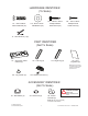
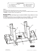
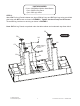
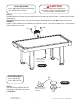


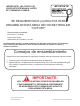
Table Of Contents

888-996-2729- 1 l l a C e c i v r e S r e m o t s u C r o F 6s t r o p S e d a l a c s E 120 2 ©
All Rights Reserved
STEP 3:
Feed P5 Electronic Scorer plug through the hole from side top rail as shown. Connect plug onto C3
Junction Box.
Attach P5 Electronic Scorer onto top rail using pre-drilled pilot holes with H4 Screws as shown in
FIGURE 3.
Install 3 "AAA" batteries (not included) into electronic scorer. To preserve battery life - turn electronic
scorer off when not in use.
PARTS REQUIRED:
2 pcs - H4 Phillips Round Head Screw
1 pc - P5 Electronic Scorer
FIGURE 3
H4
H4
P5
STEP 4:
Peel the backing off A3 Felt Pad
and attach to A1 Striker as shown
in FIGURE 4.
PARTS REQUIRED:
2 pcs - A1 Striker
2 pcs - A3 Felt Pad
THIS STEP REQUIRES TWO OR MORE ADULTS.
VERY CAREFULLY TURN THE TABLE OVER AND SET IT ON
ITS LEGS. BE CAREFUL, THE TABLE IS HEAVY.
A3
A1
FIGURE 4
Blower
Motor Cord with
ON/OFF Switch
NOTE: A3 Felt Pads may
already be attached to
A1 Strikers.
CAUTION: