ATN PS-15 o p e r a t o r s ’s m a n u a l Important Export Restrictions! Commodities, products, technologies and services contained in this manual are subject to one or more of the export control laws and regulations of the U.S. Government and they fall under the control jurisdiction of either the US Department of State or the US BISDepar tment of Commerce.
Manual (PS-15)001 Revision 1 - May 2009 The information in this manual furnished for information use only, is subject to change without notice, is not to be construed as a commitment by ATN Corp. ATN Corp. assumes no responsibility or liability for any errors or inaccuracies that may appear in this book. © 2009 ATN Corp. All right reserved.
SAFETY SUMMARY CAUTIONS • The ATN PS-15 is a precision optical instrument and must be handled carefully at all times to prevent damage. • Do not scratch the external lens surfaces or touch them with your fingers. • Wiping demisting shield with lens paper while wet or with wet lens paper can damage the coating. • To protect the image intensifier, keep the lens caps on the objective lenses when the goggles are not in use or when checked out in daylight conditions.
NOTES • At operating temperatures below –20°C (–4°F), alkaline batteries are not recommended, as operating life will be severely reduced. Lithium-iron disulfide 1.5V AA batteries or equivalent should be used below –20°C (–4°F). • The IR illuminator principally serves to let you see in the scarcely-lit surroundings at a viewing range of up to 3 meters optimally.
TABLE OF CONTENTS Section Title Page Safety Summary a Table Of Contents List of Figures List of Tables How To Use This Manual i ii iii iv Section I II III IV V VI General Information Equipment Description Mounting Procedures Operating Procedures Operational Defects Maintenance 1-1 2-1 3-1 4-1 5-1 6-1 Appendix A End Item Components A-1 Appendix B Repair Parts List B-1 Index IND-1 i
LIST OF FIGURES Figure Title ii Page 1-1 Night Vision goggles 1-2 2-1 2-2 ATN PS-15 Major Components ATN PS-15 Optional Components 2-4 2-4 3-1 3-2 3-3 3-4 3-5 3-6 3-7 Attaching ATN PS-15 to Head Mount Attaching ATN PS-15 to Helmet Mount Mounting the Picatinny Adapter to the ATN PS-15 ATN PS-15 with IR450 Mounting camera to the ATN PS-15 Mounting camcorder to the ATN PS-15 Mounting 3x Lens to the ATN PS-15 3-2 3-3 3-4 3-4 3-5 3-5 3-6 4-1 4-2 4-3 4-4 CR123A Battery Installation AA Battery Install
LIST OF TABLES Table Title Page 2-1 ATN PS-15 Major Components 2-5 4-1 Battery Life 4-2 6-1 Preventive Maintenance Checks and Service for the ATN PS-15 6-2 6-2 Operator Troubleshooting for the ATN PS-15 6-8 A-1 ATN PS-15 End Item Components A-1 B-1 ATN PS-15 Repair Parts List B-1 iii
HOW TO USE THIS MANUAL Usage Please make sure you have familiarized yourself with t h e e n t i r e m a n u a l b e fo r e o p e r at i n g t h e e q u i p m e n t . Read t he c o m p l ete m aintenan c e instr u c t i o ns b efore p er for m in g m ainte nan c e an d fo ll ow all WA R N I N G S , CAUTIONS, and NOTES. Manual Overview The manual contains sections for Operating and Maintaining the night vision goggles ATN PS-15. Components of End Item are in Appendix A. Repair Parts List is in Appendix B.
SECTION I GENERAL INFORMATION 1-1
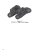
Figure 1-1 ATN PS-15 - Night Vision Goggles 1-2
1-1 GENERAL INFORMATION a. Type of Manual Operator (Including Repair Parts List). b. Model Number and basic description ATN PS-15 – Multi-Use Night Vision Goggles c. Supplier American Technologies Network Corp. 1341 San Mateo Avenue, South San Francisco, CA 94080 USA d. Purpose of Equipment To provide the user with the ability to observe at night under moonlight and starlight conditions.
1-2 WARRANTY INFORMATION This item shall conform to design, manufacturing, and performance requirements and be free from defects in material and workmanship for a period of two (2) years from the date of acceptance. If item is defective, notify ATN or point of purchase contact. 1-3 TECHNICAL INFORMATION For technical information contact ATN Corp. directly at (650 ) 989 - 5100, or info@atncorp.com or your point of purchase contact.
SECTION II EQUIPMENT Description 2-1
2.1 SYSTEM DESCRIPTION The ATN PS-15 is a hand-held, head-mounted or helmetmounted night vision system that enables walking, short-range surveillance, map reading, vehicle maintenance, and administering first aid in both moonlight and starlight. Each unit allows for vertical adjustment (by using head straps), fore-and-aft adjustment, objective lens focus, and eyepiece focus. The device is also equipped with an infrared light-emitting source.
indicator turns on, the goggles will automatically shut-off. The indicator light starts slowly flickering when the Automatic Protective System is off. The Automatic Shut-off System turn the unit off if the operation control not used more then 60 minutes. 2.2 WEIGHT, DIMENSIONS, AND PERFORMANCE Weight and Dimension Weight (with battery) 700 grams Length 120 mm Width 114 mm Height 69 mm PERFOMANCE Magnification 1X f-Number 1.2 Field of View 40 degrees Eyepiece Diopter Adj.
2.
Table 2-1 ATN PS-15 Major Components ITEM DESCRIPTIONKit Components Kit Components 1 Night Vision goggles 2 Lens Caps 3 Eye-cups 4 Soft Carrying Case 5 Operator's Manual 6 Battery 123A Lithium 7 Battery AA Alkaline 8 Battery Adapter 9 Headmount Assembly 10 Brow Pads Optional Components 1 3X Afocal Lenses (pair) 2 Camera/Camcorder Adapter 3 Demist Shields 4 Sacrificial Windows 5 Picatinny Adapter 6 Flip-up Helmet Mount 7 IR-450 IR illuminator 8 Shoulder Strap 9 Hard Shipping/
STANDARD KIT COMPONENTS 1) Night Vision goggles The binocular night vision device with 1x magnification. 2) Lens Caps The caps used to protect the lenses and to test the unit in daylight. 3) Eye-cups The rubber cups used to protect eyepiece and for operator’s comfort. 4) Soft Carrying Case A protective bag used to store ATN PS-15 and its accessories. 5) Operator’s Manual Provides equipment description, use of operator controls and preventative maintenance checks and service.
9) Headmount Assembly Adjustable universal assembly that secures the ATN PS-15 to the operator’s head providing hands-free operation. 10) Brow Pads Changeable pads for secure head mount fit. OPTIONAL COMPONENTS 1) 3X Afocal Lenses Mountable on the ATN PS15 to enhance range performance. Note: FOV reduction till 13 degrees. 2) Camera/Camcorder Adapter Mounts onto the ATN PS15 eyepiece to connect a camera/camcorder for night vision photography/filming purposes.
7) IR-450 IR illuminator A 450 mW infrared illuminator is powerfull for long range night vision in the total darkness. 8) Shoulder Strap 9) Hard Shipping/Storage Case A protective case used for shipping/storage of ATN PS-15 and its accessories.
SECTION III MOUNTING PROCEDURES 3-1
3.1 MOUNTING PROCEDURES A. Mounting the ATN PS-15 to a HeadMount To mount the ATN PS-15 to a headmount, perform the following: 1. Loosen the screw (A). Push the button (B) and insert the rail of the PS-15 into the socket (C) of the headset. 2. Place the headmount with PS-15 on your a head. 3. Loosen the screw (A) and move the unit along the rail for eye relief adjustment. 4. The PS-15 headmount has a flip-up mechanism.
B. Mounting the ATN PS-15 to a helmet Attachment of ATN PS-15 to a standard PASGT helmet. The Helmet mount fits securely onto helmet via a rugged strapping assembly and grooved hooks. With helmet mount, the PS-15 can be positioned directly in front of the user’s eyes or flipped up out of the viewing position. 1. Install the mount onto the helmet as shown on the picture. 2. Tighten and fix the straps (A) 3. Attach the goggles to the rail. 4. Loosen screw (C).
C. Mounting the Picatinny Adapter to the ATN PS-15 Mount Picatinny adapter(A) onto one of the rails on the goggles. Tighten two fixing screws(B) of the adapter. A B Figure 3-3 Mounting the Picatinny Adapter to the ATN PS-15 D. Mounting IR450 to the ATN PS-15 IR450 may be mounted on the goggles through the Picatinny adapter. 1. Install the Picatinny Adapter on one of the goggles rails (See 3.1.F). 2. Loosen the IR450 fixing screw. 3. Mount the IR450 on the Picatinny Adapter and tighten the fixing screw.
E. Mounting Camera/Camcorder to the ATN PS-15 1. Screw Camera Adapter(A) into the front lens of a photographic camera (thread M52x0.75) or a video camera (use adapter ring(C) threaded M37x0.75). 2. Remove the rubber eyecup off one of the goggles eyepieces. 3. Connect the adapter with the eyepiece and gently tighten 3 fixing screws(B) on the adapter.
F. Mounting 3x Lens to the ATN PS-15 The 3x lenses are afocal lenses which can be screwed directly into the existing 1x front lenses of the PS15.
SECTION IV OPERATING PROCEDURES 4-1
4.1 OPERATING INSTRUCTIONS a. Battery Installation CAUTION To protect the image intensifier, keep the lens caps on the objective lenses when the goggles are not in use or when they are checked out in daylight conditions. NOTE At operating temperatures below –20°C (–4°F), alkaline batteries are not recommended, as operating life will be severely reduced. Lithium-iron disulfide 1.5V AA batteries or equivalent should be used below –20°C (–4°F).
Install CR123A battery as follows: 1. Unscrew the battery cap (A) and insert the battery (B), observing the polarity as indicated. 2. Replace the battery cap (A) and screw cap. 3. Please make sure the cap comes in assembly with the battery adapter.
Install standard AA batteries as follows: 1. Unscrew the battery cap (A). 2. Unscrew the CR123 battery adapter(B) from the cap. 3. Insert AA battery, observing the polarity as indicated. 4. Put on the battery cap and screw it hand-tight. B C A Figure 4-2 AA Battery Installation b. Mechanical Functions The mechanical functions of the ATN PS-15 allow for variations of the physical features of individual operators and provide for operating the system.
Rotate the operation knob from “OFF” position to “ON” position to turn the unit on. The protective lens covers shall be attached to the lens. Do not turn the unit on in daytime without the protective lens caps on. You should see green glow in the eyepieces. To turn the unit off, rotate the operation knob (A) from “ON” to “OFF” position. You may adjust the unit diopters by rotating the eyepiece rings (B). The total dioptric range is covered in 1/2 revolution.
c. Infrared (IR) Illuminator Operations CAUTION The IR illuminator is a light source that is invisible to the unaided eye made use of in the conditions of extreme darkness. Please keep in mind this illuminator functioning can be easily detected by other people who use night vision devices, too. NOTE The IR illuminator principally serves to let you see in the scarcely-lit surroundings at a viewing range of up to 3 meters optimally. IR Illuminator gets activated when the operation knob is in “IR” position.
SECTION V OPERATIONAL DEFECTS 5-1
5-1 ZEROING OPERATIONAL DEFECTS Operational defects refer to the reliability of the image intensifiers and are an evidence of instability. Their identification shall be a valid reason to immediately refuse to accept the ATN PS-15. These include shading, edge glow, flashing, flickering, and intermittent operation. a. Shading If shading is persistent, you will not see a fully circular image (Figure 5-1). Shading is very dark and you cannot see an image through it.
b. Edge Glow Edge glow is a bright area (sometimes sparkling) in the outer portion of the viewing area (see Figure 5-2). To check for edge glow, block out all light by cupping a hand over the lenses. If the image tubes are displaying edge glow the bright area will still show up. Contact ATN or point of purchase for warranty/repair procedures. Figure 5-2 Edge Glow c. Flashing, Flickering, or Intermittent Operation The image may appear to flicker or flash.
rejection, warranty or repair please ATN or point of purchase for warranty/repair procedures. 1. Bright Spots. A bright spot is a small, non-uniform, bright area that may flicker or appear constant (Figure 5-3). Not all bright spots make the ATN PS-15 rejectable. Cup your hand over the lenses to block out all light. If the bright spot remains, return the ATN PS-15. Bright spots usually go away when the light is blocked out. Make sure any bright spot is not simply a bright area in the scene you are viewing.
you are viewing. Emission points are acceptable if they do not interfere with the usability of the device. 3. Black Spots. These are cosmetic blemishes in the image intensifiers or dirt or debris between the lenses. Black spots are acceptable as long as they do not interfere with viewing the image. No action is required if this condition is present unless the spots interfere with the usability of the device. 4. Fixed-Pattern Noise.
is present unless it interferes with the viewing the image and interferes with the users usability of the device.
SECTION VI MAINTENANCE 6-1
6-2 Interval Before Before/After Before/After Item No. 1. 2. 3. Inspect for cracks or damage. Scratches and gouges are OK if opera- Cracked or damaged. tion is not affected External Surfaces Scratches or chips hinder vision with goggles turned on, or if cracks are present. Fault not corrected. Not Current. Inspect lenses for dirt, fingerprint residue, chips, or cracks. If necessary, clean and dry lens with water and lens tissue. Goggles • Open carrying case, inventory items.
6-3 Interval Before/After Before/After Before/After Before/After Before/After Item No. 4. 5. 6. 7. 8. Inspect for cracked, torn, or missing lens caps. Rotate objective lenses focus rings to ensure free movement. Objective Lens Focus Rings Lens Caps Inspect for dirt, dust, and cracked or torn cups. Inspect for bent, broken or improperly fitting eyecups. If necessary, clean with water. Binding or not moving freely. Binding, not moving freely or too loose.
6-4 Damage causes straps or pads to be unserviceable. Damaged, latch won’t work or too loose. Binding, damaged or non-operational slide mechanism. Inspect for cuts, tears, fraying, holes, cracks, or defective fasteners. Inspect for dirt, dust, or corrosion. Insert ATN PS-15 latch into socket to verify secure attachment of ATN PS-15 to headmount. If necessary, clean socket with water. Press the socket-release button and check for free motion. Inspect for damage.
6-5 Before/After 13. Headmount / Helmet Mount Adapter Inspect for dirt, dust, or corrosion. Insert adapter into headmount or helmet mount socket to verify secure attachment. Location Item to Procedure Check/Service Damaged, will not latch securely. Not functioning at optimal level If The demist coating on the demist shield can be damaged if cleaned while wet or cleaned with wet lens paper. Clean only when the demist shield is dry and only use dry lens paper. CAUTION Interval Item No. Table 6.
6-6 Interval Before/After Before/After Before/After Before/After Before/After Item No. 15. 16. 17. 18. 19. Damage or scratches hinder vision. Inspect optical surface for dirt, dust, scratches or cracks. Neck Cord Carrying Case Inspect for cuts, tears, or excess wear or damaged clips. Remove all items and shake out loose dirt or foreign material. Inspect for tears, cuts, excess wear or damage to mounting clips. Damage or scratches hinder vision with ATN PS-15 on.
6-2 OPERATOR TROUBLESHOOTING Table 6-2 lists common malfunctions that you may find in your equipment. Perform the tests, inspections, and corrective actions in the order they appear in the table. This table cannot list all the malfunctions that may occur, all the tests and inspections needed to find the fault, or all the corrective actions needed to correct the fault. If the equipment malfunction is not listed or actions listed do not correct the fault, notify ATN or your point of Purchase.
6-8 5. Light visible around eyecups • Check objective lenses or eyepieces focus. 4. Poor image quality • Readjust for proper eye-relief distance. • If eyecups are defective, refer to higher level of maintenance. • Check eyecups for resiliency. •Clean lenses surface. • If image quality is still poor, refer to higher level of maintenance. • Check eye-relief distance. • Check for fogging or dirt on lenses. Refer to higher level of maintenance. Visual. 3. IR indicator fails to activate. •Refocus.
6-9 10. Helmet mount will not tighten to helmet. Inspect mounting hardware for damage. If damaged, refer to higher level of maintenance. • If damaged, return both headmount or head/helmet mount adapter to higher level of maintenance. Clean socket and latch. • • If damaged, refer to higher level of maintenance. 9. Headmount • Check socket or latch for dirt. or helmet mount • Check socket or latch for damage. socket and head/ helmet mount adapter latch do not catch.
6-3 CLEANING THE ATN PS-15 CAUTION The ATN PS-15 is a precision optical instrument and must be handled carefully at all times to prevent damage. Do not scratch the external lens surfaces or touch them with your fingers. Wiping demisting shield with lens paper while wet or with wet lens paper can damage the coating. Clean goggles with water, if necessary, and dry thoroughly. Clean lenses with lens paper (and water, if necessary, except for demisting shields). 6-4 HEADMOUNT MAINTENANCE a.
b. Neckpad Reinstallation During operation of the goggles, it is possible for the neckpad to become separated from its position on the headband. Perform the following procedures to reinstall the neckpad. 1. Lift the upper headband strap retention tab (see Figure 6-1), allowing the neckpad strap to be inserted underneath. 2. Slip the neckpad strap all the way under the upper strap retention tab and then pull the lower part of the neckpad strap under the lower strap retention tab. 3.
c. Lacing the Sliding Bar Buckle While donning and adjusting the headmount, it is possible for a strap to slip out of a slide fastener. Perform the following procedure to replace the strap and sliding bar buckle. Thread the strap from the inside of the buckle over the moveable sliding bar (see Figure 6-2). Thread the strap back through the buckle but this time under the sliding bar and over the serrated part of the buckle.
6-5 Tube Maintenance / Replacement 1. Unscrew the eyepiece (E) from the case of device (A). 2. Unscrew the lock ring (D) from the case of device. 3. Extract the light guide (C) from the case of device. 4. Extract the tube (B) to be replaced from the case of device (A). 5. Introduce the new tube (B) into the case of device (A). 6. Set the light guide (C) onto the place in the case. 7. Screw the lock ring (D) into the case of device. 8. Screw the eyepiece (E) into the case of device (A).
APPENDIX A END ITEM COMPONENTS TABLE A-1 ATN PS-15 End Item Componennents ITEM 1. 2. 3. 4. 5. 6. 7. 8. 9. 10. 11. 12. 14. 16. 17. 18. A-1 DESCRIPTION ATN PS-15 Goggles Assembly (without Image Intensifier Tube) Swing Arm Interface, Head/Helmet Operator Manual Demist Shields, Eyepieces Soft Carrying Case Sacrificial Windows Should Strap Head Mount Assembly Brow Pad Assembly (Small) Brow Pad Assembly (Medium) Brow Pad Assembly (Large) Lens Caps Eye Cup Assemblies CR123A 3.
APPENDIX B REPAIR PARTS LIST TABLE B-1 ATN PS-15 Repair Parts List ITEM 1. 2. ALT 3. 4. 5. 6. 7. 8. 9. 10. 11. 12. 13. 14. 15. 16. 17. 18. 19. 20. 21. 22. 23.
index A ABBREVIATIONS, 1-4 B Battery Installation, 4-2 Battery Life, 4-2 Black Spots, 5-5 Bright Spots, 5-4 C CAUTIONS, a, 4-2 Chicken Wire, 5-5 CLEANING, 6-10 Cosmetic Blemishes, 5-3 D diopter adjustment, 4-5, 6-3, 6-9 E Edge Glow, 5-3, 6-4 Emission Points, 5-5 END ITEM COMPONENTS, A-1 Equipment Limitations, b eye relief, 2-3, 4-5 Eyepiece Diopter Adj.
IR illuminator, a, 4-6, 6-8 L Length, 2-3 M Magnification, 2-3 MAINTENANCE, 6-1, 6-8 - HEADMOUNT, 6-10 - PREVENTIVE, 6-2 Mechanical Functions, 4-5 MOUNTING PROCEDURES, 3-2, 4-5 O objective lens focus, 2-2, 4-5, 6-3 On/Off/On IR control, 4-5 OPERATING INSTRUCTIONS, 4-2 OPERATIONAL DEFECTS, 5-2, 6-4 OPERATOR TROUBLESHOOTING, 6-7 P Power Requirements, 2-3 R REPAIR PARTS, B-1 S SAFETY SUMMARY, a Shading, 5-2, 6-4 SYSTEM DESCRIPTION, 2-2 T TECHNICAL INFORMATION, 1-4, info-1 V Voltage, 2-3 W WARRANTY INFORMATION,
For customer service and technical support, please contact American Technologies Network Corp. North American Office: 1341 San Mateo Avenue South San Francisco, CA 94080 phone: 800-910-2862, 650-989-5100 fax: 650-875-0129 European Office: phone: 44(0)870-0111286 fax: 44(0) 845-3349142 The following countries can use our toll free number 00 800 9102-8620 Austria, France, Germany, Holland, Italy, Spain, Sweden, Switzerland www.atncorp.