
Installation manual


4.2 Ballast frame Method
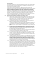
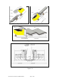
4.2.1 Assemble the relevant frame, as shown in Figure 4.2 below, using the supplied
nuts, bolts and washers (additional assembly instructions may be found in the frame
shipping box).
1. Fixing foot
2. Ballasting frame
3. Bracing strut
4. Solar Panel support
5. Upright
1 or 2 Module Long 2 or 3 Module Standard
Figure 4.2
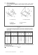
4.2.2 Position the frame in the required area on the roof, and ballast the frame with
concrete slabs. The required weight of the slabs for each solar panel can be found in
table 2, below.
Wind area Area I Area II Area III
Sol. panel type
Sol. panel weight
Frame weight
1-mod 2-mod 3-mod
37 54 80
30 30 30
1-mod 2-mod 3-mod
37 54 80
30 30 30
1-mod 2-mod 3-mod
37 54 80
30 30 30
Max height (m) Ballast weight (kg) Ballast weight (kg) Ballast weight (kg)
3
6
9
12
15
20
25
30
35
172 395 608
241 532 ***
282 614 ***
316 682 ***
340 *** ***
374 *** ***
402 *** ***
422 *** ***
443 *** ***
118 285 444
183 415 639
224 497 ***
254 559 ***
278 607 ***
309 668 ***
337 *** ***
387 *** ***
378 *** ***
90 231 362
135 320 495
172 395 608
200 419 690
220 450 ***
251 552 ***
275 600 ***
296 641 ***
313 675 ***
The ballast shown in the table must be distributed 2/3 to the back and 1/3 to the front of the frame
These figures are a guide only, the ballast weight for a particular site should be calculated
by a qualified engineer.
See table 1 for wind area codes.
Note 1 module = 1.38m
2
, 2 module = 2.75 m
2
, 3 module = 4.12 m
2
Table 2
MonoSolar & Solar Panels Installation Manual Page 10 of 29