ATMOS HEATING SYSTEMS MonoSolar and Solar Panels Installation Manual THIS MANUAL IS TO BE LEFT WITH THE HOUSEHOLDER AFTER INSTALLATION Atmos Heating Systems West March Daventry Northants NN11 4SA Tel: 01327 871990 Fax: 01327 871905 e-mail: sales@atmos.uk.com internet: www.atmos.uk.com Revised 11.5.
MonoSolar & Solar Panels Installation Manual Page 2 of 29
Contents 1. 2. 3. 4. 5. 6. 7. 8. 9. 10. Introduction and Location 1.1 Introduction 1.2 Selecting the location of the Solar Panel and Tank Installing Roof-Integrated Solar Panels Installing Roof-Mounted Solar Panels Installing Solar Panels on Flat Roofs 4.1 Fixed Frame Method 4.2 Ballast Frame Method Installing the MonoSolar 5.1 Requirements 5.2 Assembly 5.3 Connecting the panel 5.4 Connecting the Domestic water circuit 5.5 Installing the Panel Sensor 5.6 Electrical Wiring/connections 5.
1.0 1.1 Introduction and Location Introduction The Atmos MonoSolar makes use of advanced technology to produce hot water. It consists of a 100 litre insulated thermal storage tank, a heat exchanger, a multi speed pump, an electronic control module and a solar panel. Water from the storage tank is circulated around the solar panel, gaining heat from the sun.
The Controller The electronic control unit is neatly housed within the top of the tank, complete with a cover plate, which can only be removed with a screwdriver. It includes the sensor circuits for the tank and the solar panel. On the front face of the housing there is a light panel to tell the customer the temperature of the tank water and ‘Warming Up indication.
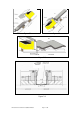
2.0 Installing Roof-Integrated Solar Panels 2.1 2.2 2.3 2.4 2.5 2.6 2.7 (For pantiles, etc, but not slates) Before commencing installation, please ensure that the flashing kit is correct for the size and type of panel configuration being used. For a single panel, it should contain the following items:1 x lead bib mounted on wooden lath, with solar panel clips. 2 x side flashings. 1 x top flashing.
Figure 2.1 Figure 2.2 Figure 2.3 Zinc Joining Channel Figure 2.
3.0 Installing Roof-Mounted Solar Panels. (For slate tiles) A special surface mounting system is available for slate tiles. Contact Atmos for details. 4.0 Installing Solar Panels on Flat Roofs Solar panels may be installed on flat roofs using a separate A-frame. The frame may be secured to the roof by screws/bolts through the feet, or by ballasting. The securing plates for these two types are different, please ensure you have the correct frame for the chosen method.
Maximum building height and strength of the screws/bolts to be used to connect the base plate to the roof. Max.
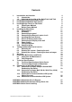
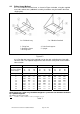
4.2 Ballast frame Method 4.2.1 Assemble the relevant frame, as shown in Figure 4.2 below, using the supplied nuts, bolts and washers (additional assembly instructions may be found in the frame shipping box). 1 or 2 Module Long 1. Fixing foot 2. Ballasting frame 3. Bracing strut 2 or 3 Module Standard 4. Solar Panel support 5. Upright Figure 4.2 4.2.2 Position the frame in the required area on the roof, and ballast the frame with concrete slabs.
5.0 5.1 Installing the MonoSolar Requirements See also sections 1.2.5 & 1.2.6. If the distance between the bottom of the MonoSolar and the top of the panel is greater than 6.0 metres, then a drain back vessel must be fitted. See Fig 5.3 & 5.4. Alternatively a second pump can be fitted, increasing the max. distance to 11.0m.
Figure 5.
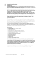
Figure 5.3 Note Solar panel has RED label marked FROM COLLECTOR. (ie Panel Flow). Solar panel has BLUE label marked TO COLLECTOR. (ie Panel Return). All solar panel pipes must have a fall of 40mm/metre or better and be insulated.
Figure 5.4 Note Solar panel has RED label marked FROM COLLECTOR. (ie Panel Flow). Solar panel has BLUE label marked TO COLLECTOR. (ie Panel Return). All solar panel pipes must have a fall of 40mm/metre or better and be insulated.
5.3 Connecting the panel 5.3.1 5.3.2 5.3.3 5.3.4 5.3.5 5.4 Do not use plastic pipes. Connect the 10mm solar panel return pipe to the elbow. Connect the 8mm solar panel flow pipe to the T-piece, feeding this pipe through the black grommet of the connection plate. Use compression fittings. Make sure that all pipes are protected by the roof insulation, using fibreglass and tape the back of the panel with aluminium tape. Do not use PUP foam.
5.5 Installing the Solar Panel Sensor 5.5.1 5.5.2 5.6 Electrical Wiring/connections 5.6.1 5.6.2 5.6.3 5.7 The panel sensor must be fixed in place into the left or right opening on the side of the panel by means of a clamping arrangement. Note that the sensor may be supplied with the panel and clamped in position. Check the screws for tightness. Seal the sensor opening with insulating material. The electrical wiring of the MonoSolar is complete and should not be altered or adjusted in any way.
5.8 Power Supply The MonoSolar requires a 230 volts, 3 Amp, earthed electrical supply via either a standard plug, or switched fuse spur. 5.9 Filling the System 5.9.1 5.9.2 Remove the plug on the T-piece. Open the water level drain valve at the riser pipe. This level is the filling level (see Fig 5.5). 5.9.3 Connect the filling hose to the filling tap connection and open the tap. Fill the appliance with clean drinking water. You can hear the tank filling up.
6.0 6.1 Taking the MonoSolar out of service Switching off The MonoSolar can be switched of by unplugging it, preferably in the morning or evening, when the pump is not running. 6.2 Draining the system – Draining the tank 6.2.1 6.2.2 6.2.3 6.3 Let the tank cool down by running the domestic hot water until all lamps on the display are off. Immediately disconnect the electrical supply. Drain with a hose connected to the drain cock at the base of the tank.
8.0 8.1 Inspection, Maintenance and Faults Inspection and Maintenance The Atmos MonoSolar system is built from maintenance free components. However, it is advisable to inspect the following annually:Control Check the wiring and check if the pump starts running when there is sufficient daylight. (The hot water tap can be opened when the tank is too hot.) Pipes Check the pipes if they are well supported within the roof insulation and not bent. Also check the pipe insulation and other insulation.
8.2 Fault Diagnosis Condition 1. The display does not give any indication in sunny periods. 2. The MonoSolar does not start operating even though the sun shines and the display works. 3. You hear the sound of dripping water in the tank. 4. You can hear the pump running. 5. The panel ‘whistles’ whenever the pump is running. 6. The temperature on the display does not change while the MonoSolar has been operating for a number of hours.
9.0 9.1 Technical Specifications Technical Specification of Solar Panels TYPE ZEN MODELS: Measurements and weights: B A A D E F C G I J H K (or Collectors) MODEL HEIGHT mm A B C D E F G H I J K 910 1776 910 1776 3491 910 1776 2596 3433 4276 5119 X WIDTH mm WEIGHT kgs 910 910 1776 1751 910 3491 2596 1776 1776 1776 1776 18 31 31 55 60 60 84 84 117 146 175 APERTURE AREA – m2 0.69 1.38 1.38 2.75 2.76 2.76 4.12 4.12 5.50 6.88 8.
9.2 Technical Specification of MonoSolar Contents of heated water 100 litre Solar Panel liquid Domestic drinking water Material Container Steel Insulation material of cylinder Foam (CFC Free) Max pressure container/cylinder 3 bar Max head of pump 6.5m Type heat exchanger Spiral coil Contents of heat exchanger 5 litre Material of heat exchanger Copper Panel surface 2.75m2 / 4.12m2 Annual energy generated by 2.75m2 panel according to DST (TNO Report No 99-BBI-R031) 3.
10.0 10.
10.
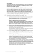
10.3 Connection to Unvented Indirect HW System (Mains Pressure) SOLAR PANEL ON ROOF Cold water inlet Unvented fittings including pressure reducing valve and 6 bar pressure relief valve refitted before MonoSolar 8mm FLOW Stop tap Thermostatic mixing valve Unvented hot water tank 10mm RETURN Blended Hot water out PUMP MONOSOLAR THERMAL STORE The Atmos MonoSolar can be installed as a pre-heat tank to an unvented hot water tank.
10.
APPENDIX 1 MonoSolar Circuit Diagram MonoSolar & Solar Panels Installation Manual Page 27 of 29
APPENDIX 2 MonoSolar Commissioning Certificate (& Check List) Check List Tick/Comment 1. Solar panel is in good location and without significant shading. 2.Solar panel orientation is correct and flow pipe taken to RED label of panel. 3. Solar panel is securely mounted and flashing secure. 4. In the case of roof – integrated panels:Lead flashing at bottom of solar panel is securely fixed, supported, dressed down onto the lower tiles.
APPENDIX 3 Solar panel Labelling The following information needs to be kept near to the solar panels (preferably displayed) :Manufacturer: Zen Year of Production: Within 1 year of installation date Country of production: Holland or Begium Glazing format: flat plate Primary absorber insulation method: glass wool Maximum stagnation temperature at 1000W/m2 and 300 C ambient: 160 deg.