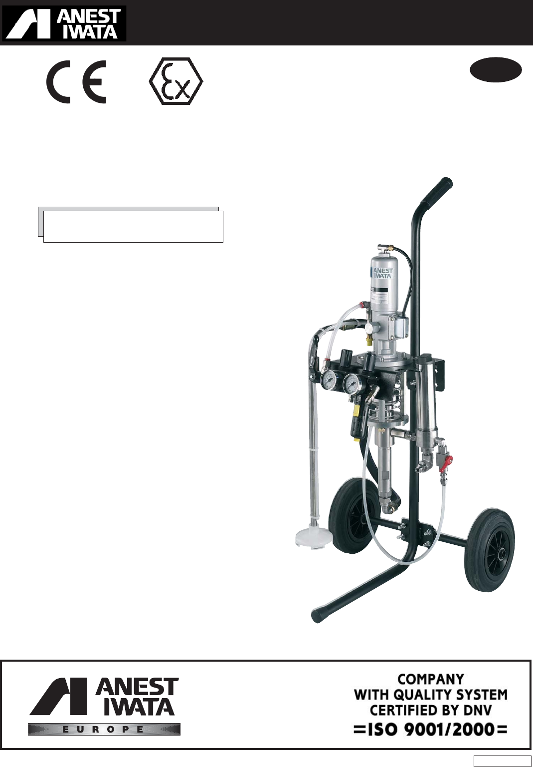
Use and maintenance manual GB MULTI SPRAY UNIT MSU-113 N ANEST IWATA Europe s.r.l. 46, Corso Vigevano 10155 Torino - Italia Tel. +39 011-24 80 868 Fax +39 011-85 19 44 www.anest-iwataeu.com e-mail: info@anest-iwataeu.com ME113NERev.
Dear Customer, We thank you for the preference you have given us and we are glad to count you among our customers. We hope the use of this equipment will satisfy you and your staff. We have first of all designed our products by focusing not only on our experience, but also on the latest mechanical innovations. The products have then been manufactured with first-rate materials and techniques and tested , considering your requirements.
GENERAL CONTENTS USE OF THE MANUAL...................................................................................................................................4 SYMBOLS USED ...........................................................................................................................................4 INFORMATIVE LETTER................................................................................................................................ 5 WARRANTY .................................
Use of the Manual The use and maintenance manual is the document accompanying the equipment from its manufacture till its dismantling. Therefore, it is an integral part of the equipment. The manual must be read before starting ANY ACTIVITY involving the equipment including its handling.
Informative letter This use and maintenance manual is an integral part of the equipment and it must be easily available to the staff in charge of its use. The user and the maintenance man must know the content of this manual. None of the descriptions or pictures contained in this manual are binding.
WARNING THIS USE AND MAINTENANCE MANUAL DOES NOT MAKE UP FOR ANY DESIGN INADEQUACY. In case of breakdown or malfunction, contact the TECHNICAL CUSTOMER CARE CUSTOMER SERVICE ANEST IWATA EUROPE s.r.l. C.so Vigevano, 46 - 10155 Torino Telefono +39 011.24.80.868 Telefax +39 011.85.19.44 E-mail: info@anest-iwataeu.com WARNING THE ORIGINAL CONFIGURATION OF THE EQUIPMENT MUST NOT BE CHANGED AT ALL.
Warranty All ANEST IWATA S.r.I products have a one-year guarantee from the invoice date, unless otherwise stated in writing. The warranty covers all manufacturing faults and material defects. Any spare part replacement or repair operations are covered only if they are carried out by our technicians at our servicing shops. The faulty parts must be sent CARRIAGE PAID. Once the components have been repaired, they will be sent CARRIAGE FORWARD to the customer.
1. TRANSPORT AND HANDLING 1.1 Transport To transport of the equipment, use only the systems described below. In any case make sure that the transport and the lifting device can bear the weight of the equipment with its packaging. WARNING ALWAYS KEEP THE PACKAGING IN A VERTICAL POSITION. WARNING IT IS ADVISABLE THAT THE STAFF IN CHARGE OF HANDLING THE EQUIPMENT WEAR PROTECTIVE GLOVES AND SAFETY SHOES. WARNING WHILE LIFTING OR HANDLING THE EQUIPMENT OR ANY OF ITS COMPONENTS CLEAR THE WORKING AREA.
1.3 Handling To handle the cardboard packaging use a trolley. To handle or displace the multi spray unit only use the cart. WARNING FOLLOW THE INSTRUCTIONS ON THE PACKAGING BEFORE HANDLING AND OPENING IT. HANDLING BY MEANS OF CART 1.4 HANDLING BY MEANS OF TROLLEY Temporary storage During transport and storage make sure the temperatures between 0 and 40° C are not exceeded. In case of storage, make sure the equipment is not put in places where there is excessive humidity.
2. PRODUCT IDENTIFICATION 2.1 Plate data The manufacturer’s identification plate is applied on the multi spray unit (see picture below). It must not be removed at all, even if the equipment is resold. For any communication with the manufacturer always mention the serial number written on the plate itself. Model Max. working pressure MSU-113N MANUFACTURED Year of manufacture MULTI SPRAY UNIT MAX AIR W. P.R. 0.68 MPa / 6.8 bar / 98 psi SERIAL NO. Serial number ANEST IWATA EUROPE s.r.l. C.
2.3 Technical specifications Model MSU-113N MSU-113N Model Model with filter (Figure 1) Model without filter (Figure 2) Dimensions mm 524x500x1020 524x500x1020 Weight kg 18 Kg 16.5 Kg Pump type Compression ratio Inlet air pipe fitting Outlet air pipe fitting Material inlet pipe fitting Material outlet pipe fitting Maximum working pressure Max fluid pressure Max.
2.4 Safety systems Several safety systems have been conceived during the multi spray unit design and manufacture to safeguard the operator, in compliance with pr EN 12621 Directive about paint.
Safety pictograms Some pictograms showing the safety warnings to be followed by anyone who is going to use it can be found on the pump. WARNING THE MANUFACTURER IS NOT TO BE HELD RESPONSIBLE FOR DAMAGE OR ACCIDENTS TO PEOPLE OR THINGS DUE TO NON-COMPLIANCE WITH THE PRESCRIBED RULES. THE OPERATOR IS THE ONLY PERSON RESPONSIBLE. 2.5 Workable products MULTI SPRAY ANEST IWATA pumps are conceived to paint ferrous material, wood and plastic.
3. OPERATION 3.1 Operation description Multi spray pumps are composed of two main parts: the pneumatic motor and the pumping unit; the pneumatic motor is provided with a pneumatic piston and with a switch for the change of the movement direction. The pumping unit is made up of an anti-wear chromium plated suction tube and rod. The packing can be adjusted. The motor’s straight and alternate movement creates an equivalent movement in the pumping unit.
4. INSTALLATION AND START 4.1 Check the purchased product Before using the pump, make sure it has not been damaged during transport or storage. Also check that all standard components are inside the packaging. 4.2 Conditions for the installation - The installer must know the ATEX classification of the installation area and also the risks deriving from a potentially explosive atmosphere, especially explosion and fire, so that he can adopt the suitable protection measures.
WARNING - CHECK THE PROPER TIGHTENING OF ALL FITTINGS, SINCE THEIR SUDDEN OPENING CAN SERIOUSLY INJURE PEOPLE. WARNING - CONSULT THE LOCAL CODE FOR DETAILED INSTRUCTIONS CONCERNING THE EARTHING OF THE WORKING AREA AND THE TYPE OF SYSTEM USED. - THE EARTH CABLE (INCLUDED IN THE SUPPLY) MUST HAVE A MINIMUM SECTION OF 1.5 MM2. - ONE END OF THE CABLE MUST BE EARTHED WHILE THE OTHER MUST BE CONNECTED TO THE COVER OF THE PNEUMATIC MOTOR PACKING. 4.4 Cautions 1.
4.
4.
5. USE 5.1 Use This section describes the multi spray unit use in compliance with the safety standards in force. We recommend reading it carefully. LIMITS AND CONDITIONS OF USE Any change of the unit can be carried out only if authorised by ANEST IWATA EUROPE technical service. If the change is not authorised, the unit is not considered as ATEX approved. Environmental condition Environment temperature: min. +5°C; max.
5.4 Prewash and adjustment of the upper packing. [Ref. figure 2 page 17 and figure 3 page 18] 1. Make sure the pump has been properly installed; (see point 4.3) 2. Immerse the suction hose (A), in the cleaning liquid (clean solvent or water according to the purchased model). 3. Place the ball valve (E) in the proper position. 4. Open the recirculation valve (C). 5. Loosen the upper packing adjusting cup (D). 6.
5.5 Start [ref. figure 2 page 17 and figure 3 page 18] Before operation, start the pump by following the operations below: 1. Dip the suction hose (A) in the tank with the product to be pumped. 2. Open the recirculation valve (C) for paint recirculation. 3. Lift and gradually turn the pressure reducer knob (G). Adjust it to a pressure slightly higher than 2.0 bar, to enable the pump to release the air. 4. Close the two-way valve for paint recirculation (C) and release the air through the gun, as well. 5.
5.6 Daily interruptions [ref. figure 2 page 17 and figure 3 page 18] 1. Upon interrupting the use of the pump: - It is not necessary to disconnect the air supply, if the interruption is short. - If the interruption period is long, turn the ball valve (E), discharge the air from the circuit and open the recirculation valve (C) to release the residual fluid pressure. 2. When the pump is stopped at the end of the working day: - Clean the fluid ducts.
5.8 Pressure release process WARNING 1. Close the air supply to the pump by turning the pressure reducer adjustment anticlockwise down to 0 bar. 2. Enable the safety catch of the multi spray gun trigger. 3. Make sure the recirculation pipe is not clogged, then gradually open the recirculation ball valve and leave it open. 4. Hold the gun tightly and lean it against the metal vessel with the paint.
6. MAINTENANCE AND INSPECTION 6.1 General notes - Observe the intervals of inspection and ordinary maintenance to ensure suitable working conditions and explosive-proof protection. - Before repairing or maintaining the internal parts, wait for the complete cooling of the unit, to prevent you from coming into contact with hot parts thus avoiding any burns. - After maintenance, make sure that all the safety measures are restored. - At the end of maintenance/repair clean the unit.
6.4 Disassembly and re-assembly procedure WARNING Before starting any maintenance operation, remove the air supply pipe and make sure the inner residual pressure has been released. 6.5 Motor group disassembly 1. Loosen the four bolts (26) and the air hose (11) then remove the seat block (A) from the main body 2. Loosen the cap (36) and remove: - spring (35); - interlock end piece (33); - washer (34); - interlock piece (32) 3. Loosen and remove the air cylinder (1) 4. Remove the split pin (28) 5.
6.7 Motor group re-assembly WARNING Remove the air feeding pipes and make sure the residual internal pressure has been released before starting any maintenance operation IMPORTANT 1. Put grease on all the moving components, o-rings and packing located inside the air cylinder. 2. Make sure the interlock piece is inserted in the rod chink 3. Make sure the block is located at the top when the piston reaches the upper end of stroke and at the bottom when the piston reaches the lower end of stroke.
1. Put the stopper (15) on the spindle set (7) NOTE: the following components are assembled on the stopper - stopper (12) - washer (13) - Y packing (14) - O-ring (6) 2.
3. Insert the spindle set (7) in the main body (27) 4. Screw the stopper (15) in the main body (27) 5. Screw the adaptor (29) and the spindle set (7); 6. Insert the split pin (28); 7.
8. Lubricate with grease and then insert the following components in the cap (36): - spring (35) - interlock end piece (33) - interlock piece (32) 9. Insert the washer (34) in the main body 10. Screw the cap (36) to the main body 11. Insert the seat block (A) in the main body and screw the four bolts (26) 12. Assemble the elbow union (21) and the special joint (8) . 13.
14. Position the packing (22) 15. By using the cross pan-head setscrew (24) screw the exhaust cover (23) to the main body. [The ground cable (60) is anchored to the exhaust cover by means of the cross pan-head setscrew (24) ] 6.8 Pneumatic motor disassembly from the fluid pump set 1. Keep the rod (41) still and unscrew the joint (29) 2.
6.9 Fluid pump set disassembly 1. Secure the suction main body (40), unscrew the suction tube (54) and slip it out. 2. Slip the rod (41) out of the suction main body (40) . 3. Loosen the adjustment nut (47) and remove the upper valve holder set (53). 4. Remove the V packing male adaptor (48), the lower V packing (49), the lower V packing female adaptor (50) and the ball (51) 5.
6.10 Fluid pump set maintenance [ref. figure on page 31] 1. Dip all components in the cleaning liquid and clean them carefully 2. Make sure the rod (41) and the suction tube (54) are not damaged. If they show deep scratches in the sliding area, replace them. 3. Check that the valve holder set (53) and the valve adaptor set (58) are not damaged, especially in the area in touch with the ball. If any anomaly is found, replace them. 4.
c) If the packing is too tight their duration shall result extremely reduced. d) A constant and suitable adjustment together with a correct maintenance allows a high packing duration. 2. Do not use grease to lubricate the sliding parts of the pump rod, since it might compromise the following painting operations. 6.12 Motor group re-assembly to the fluid pump set [ref. figure on page 31] 1.
7. TROUBLE SHOOTING Problem 1. The air pressure does not increase. 2. The paint does not flow out of the gun Cause Check Solution a) The ball valve is not in the correct position. a) Make sure the ball valve is in the proper position a) Adjust the ball valve in the proper position b) The air regulator is not open. b) Check the proper operation of the regulator b) If it is closed, open it. If it is damaged, replace it. c) Insufficient air pressure.
Problem Cause Check Solution c) Damaged or dirty valves (upper or lower). c) Disassemble both and inspect both the seat and the ball c) Clean them if they are encrusted with solidified paint residues.Otherwise, if they are damaged replace them. d) The lower V packing (inside the suction tube) is not tight. d) Disassemble the suction tube and check the wear. d) If it is enough, adjust them.
Problem 9. Paint leakage between the main body and the suction tube 36 Cause Check Solution a) Loosened suction tube a) Tighten b) The upper V packing (between the main body and the suction tube) is worn out or damaged b) Replace it 10. Paint leakage from the paint filter (model with paint filter) a) Loosened cylinder a) Tighten it 11. Air leakage from the air motor a) Worn out or damaged O-rings (ref. Page 38 components 16-20) a) Replace them b) Worn out or damaged washer (ref.
8. SECTIONS WITH SPARE PART LIST 8.1 Plunger pump set type PP7131N ref. figure on page 38 Pos.
Plunger pump set type PP7131N 38
8.2 8.3 PAINT FILTER SET For MSU 113 N : model with filter A Pos.
8.4 AIR REGULATOR SET For MSU 113 N : model with filter For MSU 113 N : model without filter Pos. Description A Air regulator set 1 1 Quick joint B.P.
8.5 STAINLESS STEEL SUCTION HOSE SET For MSU 113 N : model with filter For MSU 113 N : model without paint filter Pos.
8.6 CART SET AND PLATE FOR MSU 113 N : MODEL WITH PAINT FILTER FOR MSU 113 N : MODEL WITHOUT PAINT FILTER Pos.
9. DISMANTLING 9.1 Equipment storage If the multi spray unit is to be stored for a certain period, the following operations are recommended: Disconnect the equipment from the energy sources. Remove all residues and deposits from the pump. Cover the equipment with a waterproof tarpaulin. 9.2 Dismantling If for any reason the pump is to be dismantled, some important rules have to be followed to safeguard the environment.
ANEST IWATA Europe S.r.l. 46, Corso Vigevano 10155, Torino Italy Direct Tel. +39 011 - 24 80 868 Fax +39 011 - 22 74 406 info@anest-iwataeu.com www.anest-iwataeu.com European Sales Branches: ANEST IWATA Italia S.r.l. 46, Corso Vigevano 10155, Torino (Italy) Tel. diretto +39 011 - 24 80 868 - Fax +39 011 - 85 19 44 info@anest-iwataeu.com www.anest-iwata.it ANEST IWATA Scandinavia AB. Ögärdesvägen 6C, 433 30 PARTILLE Tel. +46 (0)31 - 340 28 60 - Fax +46 (0)31 - 340 28 69 info@anest-iwata.se www.